Continue to Site

Welcome to our site!

Electro Tech is an online community (with over 170,000 members) who enjoy talking about and building electronic circuits, projects and gadgets. To participate you need to register. Registration is free. Click here to register now.

  • Welcome to our site! Electro Tech is an online community (with over 170,000 members) who enjoy talking about and building electronic circuits, projects and gadgets. To participate you need to register. Registration is free. Click here to register now.

Isolator/Amplifier

Status
Not open for further replies.

flightline

New Member
I would really appreciate some help from someone kind with a moment to spare for a ignorant novice.

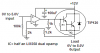
I am designing a circuit that takes a variable 0-5V, 20ma voltage from a D-A converter controlled by my computer called a LabJack and turn it into a proportional 0-8V 2A output to power an hydraulic solenoid for a flight simulator. The catch is the DA signal should be isolated to protect the expensive LabJack and I have a 12V+ regulated power supply to use. (I can get a hold of a 12V+, 12V- if I must).

A very kind gentleman made a circuit up for me (see attached) but I keep blowing the expensive UA741s trying to get it to work...Should I somehow switch the circuit to 12V+ and 12V- ???

Thank you

CP Frustrated in California.
 

Attachments

  • 5A Pos PwrSupply2.JPG
    5A Pos PwrSupply2.JPG
    76.8 KB · Views: 219
741's expensive?

The circuit has a couple of problems. The poor 741 needs a current limiting resistor between its output and the base of the 2N2222. Having the non-inverting input stuck at 6 volts means the 741 is trying to push lots of current into the base of the transistor when no signal is present from the DAC. You might try a value for the limiting resistor of 470 - 680 ohms.

The 2N2222 is trying to act like a variable resistor to control the output from the LM338. There is no feedback or adjustment in the circuit to let you make the output from the 338 agree with what you want it to be. You may need to change the op amp gain, or be able to vary the suggested (but vital) current limiting resistor.
 
The circuit doesn't work:
1) The opamp's input is biased at 6V. The input never goes that high so the output of the inverting opamp is always high and the transistor is always turned on. There is no current limiting resistor so the transistor's base current is very high and the opamp gets hot.
2) Adding a negative supply to the opamp won't make it be biased at the correct voltage of about +2.5V. It won't work.

Why turn off the LM338 on so its voltage is an unregulated about +10.5V?
Why saturate the LM338 so its voltage is about +1.3V?
 
Dear AudioGuru and J.P.

I have no idea to any of the questions you ask...they are way beyond my abilities. The metal 'tin can" 741's are expensive, I am quessing that I don't need to use one just the DIP style.

If I plead, can you make some suggestions/subsitutions to the diagram for efficent/functional circuit???

BTW the comments you make are exactly what I am finding at the workbench!!

Thank you!!!
 
Last edited:
flightline said:
Dear AudioGuru and J.P.

I have no idea to any of the questions you ask...they are way beyond my abilities. The metal 'tin can" 741's are expensive, I am quessing that I don't need to use one just the DIP style.

If I plead, can you make some suggestions/subsitutions to the diagram for efficent/functional circuit???

BTW the comments you make are exactly what I am finding at the workbench!!

Thank you!!!


Yeah just get an 8 pin DIP...there like a dollar or a little more I think...
 
The uA741 in a DIP package is $.40US each at Digikey.

Your circuit is totally wrong and probably has too many parts for whatever it is supposed to do.

It doesn't isolate.
It doesn't amplify.
What is it supposed to do?
 
My circuit has a 0V to 5.0V input and a 0v to 8.0V output at up to 2A.
Its input current at 5.0V is only 50uA.
But it doesn't have isolation.
It uses only a few parts.
 

Attachments

  • 5V to 8V at 2A.PNG
    5V to 8V at 2A.PNG
    6.4 KB · Views: 155
Thank you Mr. Guru!!

I will need isolation eventually so I don't thru sheer stupidity blow that expensive DA converter up...Thats my whole problem, isolation with amplification.
 
An optical isolator is not perfectly linear, it has an error.
The output from an optical isolator drops slowly with operating time.
 
Status
Not open for further replies.

Latest threads

New Articles From Microcontroller Tips

Back
Top