Electro Tech is an online community (with over 170,000 members) who enjoy talking about and building electronic circuits, projects and gadgets. To participate you need to register. Registration is free. Click here to register now.
Welcome to our site! Electro Tech is an online community (with over 170,000 members) who enjoy talking about and building electronic circuits, projects and gadgets. To participate you need to register. Registration is free. Click here to register now.
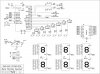
Bellow is my Sch of my project.
Are the 2n3904 the best choise?
Is there a array that would work better?
What is the lowest value for the display resistors?(max brightness)
I would suggest PNP transistors would be a far better bet, with emitters to +ve, and resistors in series with the bases. This would give you more voltage to the displays (approaching 20% more) - you would need to alter your code to make them active low, rather than active high.
Is there a array that would work better?
What is the lowest value for the display resistors?(max brightness)
The lowest value resistor is a simple ohms law problem, based on the supply voltage (minus the drop across the top and bottom drivers), and the maximum current handling of the displays. As the displays are multiplexed, you can multiply the maximum current by the number of displays - as long as it never locks up!.
i wonder what are connected to the other ends (VCC or VSS?) of the Dog,Knoter Sensor,Counter,Reset, and Stroke Reset. Do u have plans to put pull up resistors or pull down resistors?
I would suggest PNP transistors would be a far better bet, with emitters to +ve, and resistors in series with the bases. This would give you more voltage to the displays (approaching 20% more) - you would need to alter your code to make them active low, rather than active high.
Yeah, but you would need one more resistor at the base pin for each transistor. You don't need to increase the voltage because the LEDs turn ON at around 1.5V. You would still need the resistors in series with the LEDs to limit the current when using PNPs.
I found another display that is brighter, it is 5600ucd, the other was 3900ucd.
They are only in single digits, but....they are brighter. I was trying to use up the others, but...
These have the same power specs.
Would you still suggest using PNP transistors?
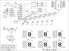
Below is a layout with PNP's. If this is the way to go, please take a look.
What should the values on the R2's and the R1's be?
Note: R2-R8 on bottom are not correct value, should be 22
R1 might, or might not, be needed - it usually won't be.
R2 isn't critical, it simply needs to pull enough current through the base of the transistor to saturate it - 1K or 2.2K should be fine, you could use the same value for R1 if you wanted to fit them.
This site uses cookies to help personalise content, tailor your experience and to keep you logged in if you register.
By continuing to use this site, you are consenting to our use of cookies.