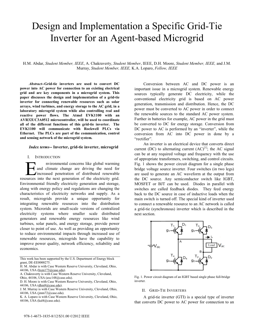
What happens at night / dead batteries?
You still need isolation and synchronisation.
Plus it is a basic regulatory requirement that the solar power side has _total_ isolation (eg. transformer) from the grid side.
And, it must shut down if the grid power fails, so it does not keep anything outside the property live.
..thanks yes, i agree with all that you say, but i mustnt have explained well enough,.......the 400V of my diagram of the top post is indeed an isolated 400V...it doesnt come from a battery......your concerns are good ones though, but the top post is a general schematic, not the finished thing, as you would know.
But the stark thing is, that it shows the basis design of a grid tied inverter, using noddy level electronics......which i believe shows that these things arent as rocket-science as the tech-world would make them out to be.
I agree with the need for synchronisation...the sim of the top post generates a sine in sync with the mains...so thats already there, yes.
So yes i agree with all you say, and all you say , is in keeping with what i show in the top post.
It shows the basis for a grid tied inverter, being sucessfully done, with what is bascially 14 year old kid electronics.
And yet it is obviously a "goody".....yes it needs the extra protections to be added, its not the finished article yet, but a very good basis, you would agree?