Continue to Site

Welcome to our site!

Electro Tech is an online community (with over 170,000 members) who enjoy talking about and building electronic circuits, projects and gadgets. To participate you need to register. Registration is free. Click here to register now.

  • Welcome to our site! Electro Tech is an online community (with over 170,000 members) who enjoy talking about and building electronic circuits, projects and gadgets. To participate you need to register. Registration is free. Click here to register now.

Is this correct?

Status
Not open for further replies.

brodin

New Member
This is the scematics for my IR transmitter. Will this work?

I am using the PWM on one of the PIC ports and the other one turns the PWM on and off. Will this work (not sure that i am using the NPN transistors right)? They are supposed to work as an AND gate.
 

Attachments

  • IR.JPG
    IR.JPG
    37.3 KB · Views: 604
Sorry. I can't answer your question, but may I ask how you made such a clean scematic drawing? Wich program?

Cheers!
Lac
 
I suggest you have a look at my PIC tutorials at **broken link removed**, my web forwarding service seems to be acting up again, and this is where it's currently hosted.

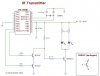
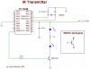
For a start, put the two IR LED's in series (with a different resistor value), you're just wasting energy for no reason having them in parallel with separate resistors. Also, you need a lower value resistor feeding the base, the hardware details in my IR tutorial show the sort of thing required.

The AND gate using the two transistors is a bit strange, and totally pointless!. If you want to use the hardware PWM (my tutorials don't, there didn't seem much point in doing so) you can simply gate it on and off by setting the PWM value to 0% for 'off', and to whatever you are using for 'on' (could be 50%, but could be less to conserve power).

My IR tutorials generate the 38KHz modulation in simple software loops, this allows you to easily send an exact number of pulses to give the pulse width you want.
 
I'll take a look at your page.

The meaning of using an AND gate is that i can always have 38kHz on one pin with PWM and the other one i can use with the command SEROUT in PicBasic Plus. Then i can send serial data over the IR-led very easy!
 
brodin said:
I'll take a look at your page.

The meaning of using an AND gate is that i can always have 38kHz on one pin with PWM and the other one i can use with the command SEROUT in PicBasic Plus. Then i can send serial data over the IR-led very easy!

I've got bad news for you (read the tutorial), it doesn't work :cry:
 
I have taken a look at your site(very good site!). I have made the modifications in the scematic. Is there any reason to why you have connected one LED to +5V then the resistor and then the other led?
I would have connected the resistance first, than the two leds. Is there any difference?
 

Attachments

  • IR2_202.jpg
    IR2_202.jpg
    30.4 KB · Views: 579
brodin said:
I have taken a look at your site(very good site!). I have made the modifications in the scematic. Is there any reason to why you have connected one LED to +5V then the resistor and then the other led?
I would have connected the resistance first, than the two leds. Is there any difference?

The only reason for it is that the layout was built like that (it saved an extra wire link), so I redrew the circuit to match - it makes no difference at all to the operation.
 
Status
Not open for further replies.

Latest threads

Back
Top