Continue to Site

Welcome to our site!

Electro Tech is an online community (with over 170,000 members) who enjoy talking about and building electronic circuits, projects and gadgets. To participate you need to register. Registration is free. Click here to register now.

  • Welcome to our site! Electro Tech is an online community (with over 170,000 members) who enjoy talking about and building electronic circuits, projects and gadgets. To participate you need to register. Registration is free. Click here to register now.

Is this circuit viable ?

Status
Not open for further replies.

Externet

Well-Known Member
Saw it when I was a kid and has been in my retina since then.

Would such thing work? What considerations to take in account, limitations and calculations for the capacitor and inductor to provide 120 degrees phase shifts ?
 

Attachments

  • P1010154.JPG
    P1010154.JPG
    525.6 KB · Views: 239
I don't believe you could get a close enough phase shift to make this work.
Getting a 120 degree phase shift with a single capacitor or a single inductor would be hard to do.
 
Saw it when I was a kid and has been in my retina since then.

Would such thing work? What considerations to take in account, limitations and calculations for the capacitor and inductor to provide 120 degrees phase shifts ?

No, it will not work.

A Perfect Capacitor or a Perfect Inductor can give you Only 90° Phase Shift - Leading and Lagging respectively. It will be less when you have something else in series - in this case the motor coil (Resistance + Inductance).

Ramesh
 
No, it will not work.

A Perfect Capacitor or a Perfect Inductor can give you Only 90° Phase Shift - Leading and Lagging respectively. It will be less when you have something else in series - in this case the motor coil (Resistance + Inductance).

Ramesh

I'm sorry to burst your bubble, but it will work.... My father built a three phase lawnmower ( Christ knows why )... Anywho!! it worked just fine he ran it off 240vac. He used it for years.
 
My AC theory is rubbish - is it possible to tune the phase shift?
 
I have been using the "Top Secret Recipe" for decades on motors up to 10 HP. It works great.
 

Attachments

  • Phasecon.jpg
    Phasecon.jpg
    259.4 KB · Views: 193
  • Phase converter.jpg
    Phase converter.jpg
    142.8 KB · Views: 190
Hi,

The key point is that the phases dont have to be perfect, they just have to be different. A stepper motor will run with phases different too even though they are not optimal. But that does not mean we'll see the full power output either though, as the best source will be what that motor was made for.

I ran a small motor (very small) with an AC input and a single capacitor. It would not run with just two wires connected it needed the third wire connected through the capacitor. That was a long time ago however and i never investigated to find out exactly why it worked.
 
I'm sorry to burst your bubble, but it will work.... My father built a three phase lawnmower ( Christ knows why )... Anywho!! it worked just fine he ran it off 240vac. He used it for years.

Are you referring to a 120° phase shift or making the motor spin?

If former, you can't burst that bubble :eek:
If latter, there is no bubble to burst :D

Ramesh
 
Hi,

Since you cant get 120 degree phase shift with a capacitor that means it just makes a phase that is different, and that's enough to push the motor. It's not enough to attain full power though. You may get enough power for your application though.

The motor i used was small and it only needed a 0.1uf capacitor, but there was enough power such that you could not stop that shaft from rotating with your fingers, yet it was a very small motor.
 
Are you referring to a 120° phase shift or making the motor spin?

If former, you can't burst that bubble :eek:
If latter, there is no bubble to burst :D

Ramesh

He asked whether the circuit would work.... The correct answer was yes!!! whether it was efficient whilst running wasn't asked for...
 
He asked whether the circuit would work.... The correct answer was yes!!! whether it was efficient whilst running wasn't asked for...

Hi there Ian,

He he, yes that's true. So i guess we are lucky he did not ask if a person could jump out of an airplane without a parachute...he he, sure they can, but they wont like the results :)
 
Hi Ian,

Oh i am happy to hear that. Talking about what people cant help doing sometimes, I cant help myself when it comes to kidding around a little sometimes and if that makes someone laugh a little that's really great as i love comedy :)
 
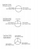
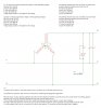
So I wanted to comment on the phase shift question concerning single phase to three phase. I am an experienced mill electrician, I also have a 2 yr degree in Electronics Technology from 1987. I am in the southern U.S., in Louisiana. In my area the local utility can supply customers with two different kinds of three phase. One is what you might call "true" three phase, the other is what we call "Wild leg". "True" has 120/120/120/208, "Wild" has 120/120/212/240. "True" comes from three primary phases (13,800V in this area) and one transformer per primary phase on the pole. They are 120 degrees out of phase to add up to a full circle of 360 degrees. "Wild" only needs two transformers; the normal 120/120/240, that we see in our homes which are 180 degrees out of phase to add up to 360 and are derived from a single primary phase; and a second transformer that produces 212V to neutral or ground from the same primary phase and is only 90 degrees out of phase from the 120/240 legs, however phase to phase is 240V.
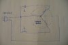
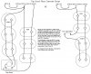
Now for the mind bending part: If you connect a three phase motor (designed for normal balanced three phase ie: {208 or 230 or 240}) to single phase 230V or 240V and use the correct capacitor start circuit, it will start and run and generate the same "wild leg" voltage on it's un-powered leg. But if you apply the correct run capacitor circuit it will produce a balanced three phase voltage (what ever it was designed for in that voltage range). That adjustment is not 90 degrees, it is 30 degrees. See the attached pic for a bit more info/explanation.
I am not saying this is a technical explanation, I am not saying the drawing is technically correct, please don't call me down on technicalities, I know I am not an engineer and don't claim to be one.

However, this is what actually happens.

Now for the really bad part of this post, I just noticed that this thread is from 2013, I just got to this forum 5 days ago and haven't gotten used to the fact that ya'll take so long to talk about things.

posting anyway LOL
 

Attachments

  • Phase angles.jpg
    Phase angles.jpg
    109.7 KB · Views: 94
Interesting, I haven't heard of a wild leg since I was in Louisiana. Actually, in the plant I was responsible for, the techs referred to the whole transformer as a "true" or a "wild". It came up when some equipment tended to "chatter" when running at certain load levels. The equipment that chattered needed bearings, seals or other maintenance more frequently and the techs eventually tied it back to the wild transformers. The plant was the last industrial site before the end of civilization and often suffered brownout as well - the site was eventually scrapped.
 
My drill press was 3 phase and ran from 1 phase for ages.
Only it didnt have the choke, just the cap.
 
L1 live
L2 neutral
L3 live via a cap
Motor wired in delta so it has no star point, and is derated to 240v
 
Status
Not open for further replies.

Latest threads

New Articles From Microcontroller Tips

Back
Top