dr peppers
New Member
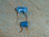
I took this off a scrap board and wondered whether its an odd capacitor or a resonator, it only has 2 pins unlike a resonator but its does look like one.
The markings are 206f 05n, the 05 looks like the date code, it'd be usefull if it was a 200kc resonator.
I cant remember what part of the board it came off, there was some digital stuff on there so it might have been a clock generator.
Sorry about the pic, best I could do, the pin spacing is 0.3".
View attachment 61607
")