Continue to Site

Welcome to our site!

Electro Tech is an online community (with over 170,000 members) who enjoy talking about and building electronic circuits, projects and gadgets. To participate you need to register. Registration is free. Click here to register now.

  • Welcome to our site! Electro Tech is an online community (with over 170,000 members) who enjoy talking about and building electronic circuits, projects and gadgets. To participate you need to register. Registration is free. Click here to register now.

Is this a good circuit?

Status
Not open for further replies.

Alpisces

New Member
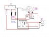
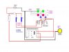
I just taught myself the fundamentals this week, and have come up with the following circuit for running the fog lights on my truck. 'ChrisP' gave me some good direction on the relay portion but I do now know anyone that can check my math (Ohm's, volts, etc.) Does this schematic have any flaws or miscalculations?


-Thanx-
 

Attachments

  • BOX_Small_161.jpg
    BOX_Small_161.jpg
    61.6 KB · Views: 497
Hi Alpisces,

The circuit looks correct, and nice and colourful.
Except for the diode 1N4001 which looks backwards.

(The battery terminals aren't marked,
so i'm going by the wire colours.)

Do you really need an indicator to tell you
that the fog-lamp is not on ?

Regards, John :)
 
The battery symbol should not be symmetrical, the long line is the positive. I don't know what the diode is for, you don't need it. In order to know if the resistors are OK, I need to know the resistance of the relay coil. If the fog light draws 25 amps, the fuse should be 30 amps at least.
 
John 1 & RusslK - I appreciate you taking your time to help me.

1. - Indicating lamps - Just for aesthetic reasons
2. - I believe the resistance on the relay is 240K [ 6v/25mA=240k ]
3. - The diode I placed there because I thought that it needed a diode to prevent a backsurge of voltage to the L.E.D's- is that what the diode is for?

I have updated the schematic per your directions.
 

Attachments

  • BOX_Small_208.jpg
    BOX_Small_208.jpg
    61.3 KB · Views: 409
6V/25mA=6/0.025=240 Ohm (not kOhm).
And yes, it looks ok now as long as relay doesn't draw any current.
With 17mA for LED and 25mA for relay, you would have total of 42mA
going through R2 which would create drop of 500Ohm*42mA=21V.
Since you car battery doesn't run that high (probably it's in 13V range)
your circuit will starve. LED will probably still work but loose brightness
while relay probably won't be able to pull in.
You could replace R1 and R2 for 6.2V zener diodes to guarantee half
voltage for the relay or you can change value for R2 to be ca 220 Ohm.
You could ask yourself why not put 12V relay and bypass R2 all
together...
 
Status
Not open for further replies.

Latest threads

New Articles From Microcontroller Tips

Back
Top