That looks far too small for the FM band at around 100MHz??
Each driven (electrically connected) dipole should be approximately 5% less than a calculated half wave, end-to-end; at 100MHz, 3 metres wavelength, that is 142.5cm (56 inches) end to end.
If the dimensions are wrong by more than a few percent it will simply not work well, if at all.
This is some design info and calculations for building a Yagi style antenna:
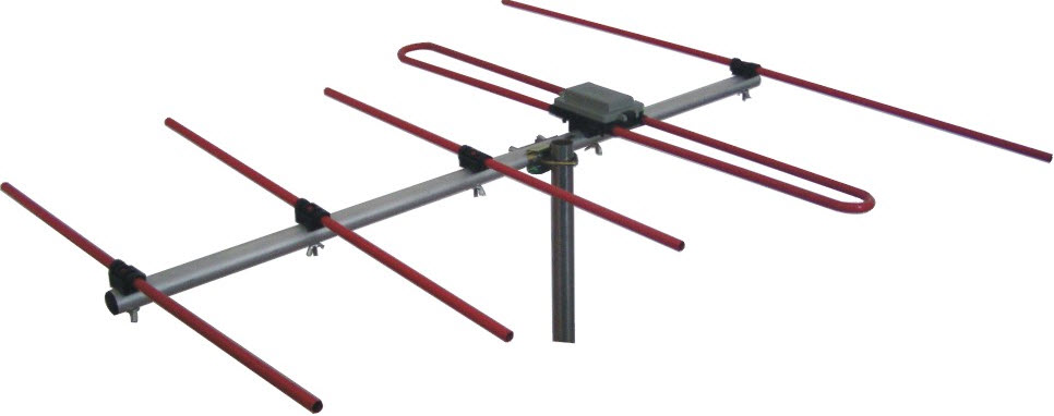
An yagi antenna, a narrow band antenna working for FM channel and consisting of a reflector, a driven element and two directors.

www.elprocus.com