Continue to Site

Welcome to our site!

Electro Tech is an online community (with over 170,000 members) who enjoy talking about and building electronic circuits, projects and gadgets. To participate you need to register. Registration is free. Click here to register now.

  • Welcome to our site! Electro Tech is an online community (with over 170,000 members) who enjoy talking about and building electronic circuits, projects and gadgets. To participate you need to register. Registration is free. Click here to register now.

IR2153

Status
Not open for further replies.
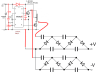
I just bought x2 IR2153 IC and i am thinking to built an inverter based on this IC. I have aphoto of the circuit. I would like to drive it at about 50khz frequency, but i am not sure at what values i have to change for that purpose. I found an exe file that it looks that it calculates the frequency when you put the capacitor and resistor values. According to the program with 13k resistor and 1nf cap i have about 51khz frequency, is that correct ? Also i am going to use x2 IRF540N Fets


https://www.electro-tech-online.com/attachments/ir2153-inverter-circuit-jpg.114984/

Mod disabled exe file for saftey

Also i would like to drive a voltage multiplier like this with the above circuit.

https://upload.wikimedia.org/wikipe...ade.svg/640px-Stacked_Villard_cascade.svg.png

What diodes would be suitable for this frequency? 1N4148 would do the job ?

Thanks.
 
Last edited by a moderator:
I would like to drive it at about 50khz frequency, but i am not sure at what values i have to change for that purpose.
There is a chart in the IC's datasheet, which shows the Rt and Ct values for various frequencies. I wouldn't rely on some anonymous exe file for the calcs.
The optimum diodes would depend on the current to be drawn from the inverter.
 
1542034151413.png

edited---------
Almost all circuits on the internet will not work! Much like almost all pills on the internet will not work. $19.95 + shipping and handling will not make you taller/longer/bigger/smaller/happier/etc.
Updated the circuit because of an error. (did not try it so there may be more errors)
 

Attachments

  • 1541983538244.png
    1541983538244.png
    39.7 KB · Views: 172
Last edited:
1N4148 would do the job ?
I very much doubt it. Unless you clamp the drain voltage of the MOSFETS it will pulse very high when they turn off and will exceed the maximum reverse voltage rating of the diode. Also, the charging current of the capacitors in the multiplier may exceed the maximum current rating of the diode.
 
Rosimpson i want to drive the voltage multyplier after the transformer without removing it.

What diodes would be suitable for that frequency? Maybe UF4007 or is even worst?
 
The strange is that in the pdf of those 2 diodes (1N4148 & UF4007) the 1N4148 looks to be much more faster than the UF so i am a bit confused.
 
The 1N400x family is 1A, 2uS turn off time. x=voltage
The UF400(1-4) is 1A 50nS
......The UF400(5-7) is 1A 75nS
The 1N4148 is 200mA, 2nS, 100V

I think you need to keep the diode speed below 100nS. Don't use the 1N400x series.
 
The 1N4148 is NOT suatable if feeding the multiplyer with 350 volts as it's PIV rating of 100 volts is too low.

Les.
 
Status
Not open for further replies.

Latest threads

New Articles From Microcontroller Tips

Back
Top