Continue to Site

Welcome to our site!

Electro Tech is an online community (with over 170,000 members) who enjoy talking about and building electronic circuits, projects and gadgets. To participate you need to register. Registration is free. Click here to register now.

  • Welcome to our site! Electro Tech is an online community (with over 170,000 members) who enjoy talking about and building electronic circuits, projects and gadgets. To participate you need to register. Registration is free. Click here to register now.

IR LED illuminator

Status
Not open for further replies.

BigJay

New Member
hello everybody
i'm trying to build an IR illuminator to use with my security cam i need it to run with a DC power supply with a current of 60A the illuminator is made of 144 IR LED. i;m a beginner in electronics so could anyone please tell me the formula to use so i can choose my resistors? i have the multisim software but it's giving me lots of error and i can't know why although i have drawn my circuit correctly. so please any help is appreciated. the circuit is made of 36 parallel set of 6 IR led and a resistor in series . thx in advance.
 
Hi BigJay,

first off there is a math error in your description.

An assembly of 36 parallel branches with six LEDs each in series totals 216 LEDs.

Connecting 36 parallel branches with four each makes the 144 you mentioned.

Anyway, the minimum supply voltage for six LEDs in series is 7.8V (number of LEDs multiplied with LED forward voltage assuming 1.3V per LED)

1.3V refers to the LD274-3, there are some with a forward voltage of 1.5V as well on the market.

To calculate for the appropriate current limiting resistor use this formula:

R(limit)=US-(NLED*Uf)/If, where R(limit) is the current limiting resistor (Ω), US is the supply voltage, NFLED is the number of LEDs connected in series, Uf is the LED forward voltage (V) and If is the LED forward current (A)

Example: US=12V, number of serial LEDs=4, Uf=1.3V, If=0.02A

R(limit)=12-(4*1.3)/0.02; R(limit)=340Ω. The closest standard resistor value is 330Ω, which you might use since most IRLEDs can be operated up to 100mA If.

The power dissipation of the current limiting resistor is calculated by the voltage drop it causes multiplied with the current flow.

P(W)=6.8V*0.02A; P=0.136W. Using a standard resistor rated 250mW suffices.

Don't use carbon film resistors and use metal film resistors instead, since carbon film resistors have a high positive temperature drift and increasing the resistance means decreased LED power.

Boncuk
 
Last edited:
I see no mention of voltage anywhere in your post, that's kind of important =) Both the DC power supply voltage under no load and under the 60 amp load, and the forward voltage of the diodes at their rated current.
 
Last edited:
Hi BigJay,

first off there is a math error in your description.

An assembly of 36 parallel branches with six LEDs each in series totals 216 LEDs.

Connecting 36 parallel branches with four each makes the 144 you mentioned.

Anyway, the minimum supply voltage for six LEDs in series is 7.8V (number of LEDs multiplied with LED forward voltage assuming 1.3V per LED)

1.3V refers to the LD274-3, there are some with a forward voltage of 1.5V as well on the market.

To calculate for the appropriate current limiting resistor use this formula:

R(limit)=US-(NLED*Uf)/If, where R(limit) is the current limiting resistor (Ω), US is the supply voltage, NFLED is the number of LEDs connected in series, Uf is the LED forward voltage (V) and If is the LED forward current (A)

Example: US=12V, number of serial LEDs=4, Uf=1.3V, If=0.02A

R(limit)=12-(4*1.3)/0.02; R(limit)=340Ω. The closest standard resistor value is 330Ω, which you might use since most IRLEDs can be operated up to 100mA If.

The power dissipation of the current limiting resistor is calculated by the voltage drop it causes multiplied with the current flow.

P(W)=6.8V*0.02A; P=0.136W. Using a standard resistor rated 250mW suffices.

Don't use carbon film resistors and use metal film resistors instead, since carbon film resistors have a high positive temperature drift and increasing the resistance means decreased LED power.

Boncuk

thank you very much Boncuk, you answered for everything i needed to know. and you are correct i have a 24 branch not 36 :p 
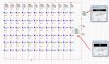
my mistake. but i'm having a prob with the multisim when simulating the circuit when i check the current between the LEDs it's giving me 5A i'm branching the multimeter in parallel with the LEDs to check it. am i doing anth wrong or is there sth i miss understood? i posted the circuit i reduced it to 12 branches of 6 LED just make my tests.
 

Attachments

  • circuit.jpg
    circuit.jpg
    293.4 KB · Views: 2,044
Last edited:
Status
Not open for further replies.

Latest threads

New Articles From Microcontroller Tips

Back
Top