Mosaic
Well-Known Member
Dakta: I know exactly what u are talking about.
I have just designed and in the final stages of testing a multigauge, multifunction controller for turbo charged engines with the following features:
1) Analog sweep & Digital Boost
2) Open & Closed loop multi map, HoT side, boost controller (PID) based on TPS, RPM & Boost pressure
Including True continuous barometric reference for mountainous rallys etc.
3) Electronic Blow off valve control and cold side EBC.
4) True turbo surge control via the cold side BOV/CBV valve at pressures BELOW the hotside wastegate spring pressure.
5) Gear shift boost launch/traction control
6) Gearshift based dynamometer for tracking turbo spool rates and optimum tuning.
7) Turbotimer
8) Auxiliary outputs configured by TPS, Boost, RPM, Oxygen/ AFR sensor. Suitable for NOS or water injection staging.
So...what u need is simple enough.
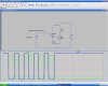
You are tapping the output of an open collector sink Transistor or N Channel MOSFET.
Therefore all u gotta do is place a 'pullup' resistor...perhaps 10K on the input to force the signal to 'your' MOSFEt high when it goes 'disconnected' from the source. Then use the circuit link I showed u to establish a True Hi and LOW drive inversion..
A pullup resistor is tied to the 12V+ power
I have just designed and in the final stages of testing a multigauge, multifunction controller for turbo charged engines with the following features:
1) Analog sweep & Digital Boost
2) Open & Closed loop multi map, HoT side, boost controller (PID) based on TPS, RPM & Boost pressure
Including True continuous barometric reference for mountainous rallys etc.
3) Electronic Blow off valve control and cold side EBC.
4) True turbo surge control via the cold side BOV/CBV valve at pressures BELOW the hotside wastegate spring pressure.
5) Gear shift boost launch/traction control
6) Gearshift based dynamometer for tracking turbo spool rates and optimum tuning.
7) Turbotimer
8) Auxiliary outputs configured by TPS, Boost, RPM, Oxygen/ AFR sensor. Suitable for NOS or water injection staging.
So...what u need is simple enough.
You are tapping the output of an open collector sink Transistor or N Channel MOSFET.
Therefore all u gotta do is place a 'pullup' resistor...perhaps 10K on the input to force the signal to 'your' MOSFEt high when it goes 'disconnected' from the source. Then use the circuit link I showed u to establish a True Hi and LOW drive inversion..
A pullup resistor is tied to the 12V+ power
Last edited:
")
")
