Continue to Site

Welcome to our site!

Electro Tech is an online community (with over 170,000 members) who enjoy talking about and building electronic circuits, projects and gadgets. To participate you need to register. Registration is free. Click here to register now.

  • Welcome to our site! Electro Tech is an online community (with over 170,000 members) who enjoy talking about and building electronic circuits, projects and gadgets. To participate you need to register. Registration is free. Click here to register now.

Inverter Output Stage Modification

Status
Not open for further replies.

Suraj143

Active Member
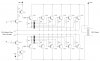
Hi I’m going to build an inverters output stage. This is my own version. I like to extend the circuit to get more kilowatts power.

This is only a BJT version later I’m going to implement a FET version as well. First I need to verify my diagram.

Note:
Don’t worry about how you power the circuit & the size of the transformer. Here we have large power banks & large transformers. So no need to worry on that.

Thanks
 

Attachments

  • Inverter Sch..JPG
    Inverter Sch..JPG
    152.8 KB · Views: 441
What are the diodes for? I've never connected a bunch of power transistors in parallel like that, but I understand it's not a very good idea becuase of current hogging. Use low value emitter resistors to mitigate that effect. Also, you're switching 12Vdirectly into the bases without anything to limit current. The transistors will just go *poof*. Why are you using obsolete 3055's? Also, the fast swiching might mean very high output voltage from your transformer, as well as high sipkes on the primary side.

Is this an experiment or a product?
 
Last edited:
Hi BrownOut thanks for your very useful ideas.

This is just a test.I can generate 50Hhz input very accurately.Only problem is the output stage for me.

Ok I'm going to use 0.22Ohms/5W emitter resistors on the output transistors.So I need 10 resistors.

Is it ok if I replace the diodes & connect 1K resistors?

Can you suggest a transistor which is commonly available? TIP3055 is very easy to find.

Also, the fast swiching might mean very high output voltage from your transformer, as well as high sipkes on the primary side.

So what are the precautions do I have to do for this?

I need to parallel more transistors later & make a 10KW inverter.

Any comments?
 
Last edited:
Hi
You don't seem to have any snubber network on the transformer primary,ie large back EMF with switching!without anything here,your tip3055's will blow.;)
 
You would probably be best off revising the switching circuit to use a Mosfet based design. Then all you would need is a gate driver IC to run each bank. You would have much higher power capacity and greater efficiency for less cost as well.

But 10 Kw at 12 volts is somewhat unrealistic being the amps are incredibly high at that level which makes all of the power handleing cables massive.
 
But 10 Kw at 12 volts is somewhat unrealistic being the amps are incredibly high at that level which makes all of the power handleing cables massive.

Yes, 500W is about as high as 12V can go really, for 10KW the massive banks of batteries may as well be wired to give a MUCH higher voltage - in fact why not wire them to give 120V or 240V, so no need for a transformer?.

Also, what use is 10KW of squarewave?, a class-D sinewave switcher directly off batteries (no transformer or inverter again) would give you a nice sinewave.
 
Ok guys I finally planned to make a 12V 500W inverter.

I'm going to use MOSFETS.IRF 540 ones.Any suggestions!!
 
Can somebody tell me how to convert a square wave to a modified or pure sine wave converter?

I can generate PWM using PIC chips as well.

The main reason I don't no how to generate a sine wave do I need a filter to make a sine wave?
 
Last edited:
The normal way modern inverters work is to use a high frequency switching supply (basically a class-D amplifier). This class-D amplifier is fed with a 50/60Hz sinewave input, resulting in a pulsewidth modulated output signal from the transformer. This is then low-pass filtered (to remove the high frequency switching waveform) using an LC filter, leaving a fairly pure sinewave output.

They are incredibly cheap to buy ready made, and I've never seen a DIY design, as it's not cost effective.
 
Ok thanks nigel for the information's.

First I'm going to make a modified sine wave inverter 12V/500W one.

I read many articles on the web.I have one question.

In normal square wave inverters one side of push pull is turn on 10mS time & off 10mS for a 50Hz generation.
But in modified sine wave inverters one side of push pull is turn on 5mS time for a 50Hz generation.

I know this is to work the MOSFETs in the active & cut off regions but is this 5mS ON time enough?
 
Last edited:
It's the lesser ON time that gives the modified sinewave - as it is, even for a squarewave one, it's essential to have a 'dead band' where both devices are OFF.
 
Ok this is the circuit I'm going to make.Is my values ok? What about snubber values??Is this is a good design?
 

Attachments

  • Inverter Sch..JPG
    Inverter Sch..JPG
    66.5 KB · Views: 164
Last edited:
A simple square-wave inverter has the peak voltage the same as the RMS voltage of a sine-wave so that the power is the same to a heater or incandescent light bulb.
A modified sine-wave inverter (really a modified square-wave) has the peak voltage the same as the peak voltage of a sine-wave so the transformer low voltage windings must be 8.5V instead of 12V. Then the peak current is 1.4 times higher than a square-wave inverter.

A CD4047 oscillator has 3 outputs which can be gated to make the modified waveform.
 
Ok thanks audioguru now I understood.So I'll change the transformer to 8.5V-0-8.5V.If I cannot find a 8.5V transformer is it ok a 12V-0-12V one?


I need to verify my values & the most important thing is that snubber values.
 
Why not use a 9-0-9V transformer which you should be able to buy?
 
If you use a 12V + 12V transformer in a modified sine-wave inverter then the output voltage will be only 163VAC instead of 230VAC.

Your inverter is extremely simple and does not heave voltage regulation so the output voltage will be higher than you expect when it has a light load and the battery is fully charged and the output voltage will be lower than you expect when the load is heavy and the battery charge is running down.
 
Hi audioguru I cannot understand how did you get the value of 163VAC if I use a 12V-0V-12V transformer?

Now I'm confused about modified sine wave.Is there any output voltage difference between modified sine wave and basic square wave designs?

I thought if I drive the primary side of a 12-0-12 transformer the output will be 230V.
But if I drive the same transformer using modified sine wave then the voltage will be different I don't know why is that ??
 
Last edited:
If you use a 12V-0V-12V transformer then the peak voltage of your modified sine-wave will be 230VAC but the RMS voltage will be 230V x 0.707= 163VAC.
 
If you use a 8.5V-0V-8.5V transformer and feed it with a 12V peak modified sine-wave then the peak output voltage will be 325VAC and the RMS will be 230VAC.
 
Status
Not open for further replies.

Latest threads

New Articles From Microcontroller Tips

Back
Top