Continue to Site

Welcome to our site!

Electro Tech is an online community (with over 170,000 members) who enjoy talking about and building electronic circuits, projects and gadgets. To participate you need to register. Registration is free. Click here to register now.

  • Welcome to our site! Electro Tech is an online community (with over 170,000 members) who enjoy talking about and building electronic circuits, projects and gadgets. To participate you need to register. Registration is free. Click here to register now.

inverter output corrupted help!

Status
Not open for further replies.

MrDestruction

New Member
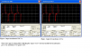
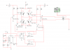
Hey guys, can u tell me what you think might be the problem with this output of my mosfet transformer circuit. I also displayed the output in my attached images. Do you think its because of the BJT's to slow switching time.

Anyways let me know what you guys think.

later guys and girls.

Mr. D.
 
Hi,

MrDestruct, your profile shows pictures that are very hard to read.
You should do them over making them larger and clearer.
You should also post them in this thread for easier viewing.

I can tell you right off that you are not driving the bipolar transistors
correctly but i would rather look at a larger schematic first.
 
The schematics were saved as a very fuzzy JPG file type instead of as a very clear GIF or PNG file type.
 
Hi,

Yes i found that rather strange too :)
 
my intention of this circuit was to see mosfet H bridge to drive a step up transformer. So i used bjt transistors to switch the mosfets. this circuit is not for building, its for simulation.

If the problem is switching time then i have reached my simulation. because i can't simulate the mosfet driver yet as i am still working on the circuit for it.

just wanted to know what was wrong with the output.
 

Attachments

  • inverter transformer output.PNG
    inverter transformer output.PNG
    279.3 KB · Views: 122
  • 555 timer inverter with transformer.PNG
    555 timer inverter with transformer.PNG
    43.5 KB · Views: 135
My bad guys, here it is let me know what you think. i know the transistors are bad choice to drive H bridge mosfets but i just needed to simulate ac curve at transformer output.

Thanks,

Mr. D.
 
Its not the transistors; they will discharge the FET gate capacitance when they turn ON. What is wrong is how long it takes to charge the FET gate capacitance through the 1K pullup resistor when the NPNs turn OFF.

You also need a series resistor between the op-amp outputs and the bases of the NPNs.

Why not use a real gate driver like this one for the low-side gate driver. Poke around on TI's web site. They make a high side driver too. Then you can lose the op-amps.
 
Last edited:
In actual circuit development, i will be using mosfet driver, but this is a simulation environment, just trying to get a square wave H bridge transformer output. I do not have a mosfet driver simulation model that i can use for this so i used transistors to switch the mosfets.

what do you think i should add to the schematic to remove this saturation. i will add 4.7K Resistors at the base of the transistor but i don't how that will help.

thank you for your help btw.

Mr. D.
 
Status
Not open for further replies.

Latest threads

New Articles From Microcontroller Tips

Back
Top