Hi,
I have a trouble interpreting the RPM signal from a 3-wire fan here. It seems that the RPM feedback signal puts a high voltage on the pin of the micro-controller to which is connected (i.e. 6V). Due to that the micro-controller behaves erratically so I have it disconnected for the time being. In the meantime, I'm really trying to figure it out how I can possibly have it work.
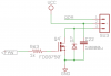
So to clear the explanation of the situation. When the fan runs, the yellow line (RPM signal) gives out a clean 5V square wave signal. However, when the fan is turned off, it has an idle DC voltage of about 6V. I'm not really sure why it is happening so. Someone suggested that I put a voltage divider in between but that mitigates the pulse signal (square wave) voltage level and it won't trigger the edge interrupt on the controller.
I'm using a regular DC brushless 12 fan and PIC18F4525. I'm attaching an image of the circuit part as well. Moreover, I kind of got the idea of designing the FET and everything off another circuit but I was wondering why the FET is connected to the ground pin of the fan instead of 12V and 12V is directly fed into the fan. I guess I don't understand how a normal DC 12V fan works and it would be greatly appreciated if someone could thoroughly explain to me.
Thanks loads in advance,
Jeff
I have a trouble interpreting the RPM signal from a 3-wire fan here. It seems that the RPM feedback signal puts a high voltage on the pin of the micro-controller to which is connected (i.e. 6V). Due to that the micro-controller behaves erratically so I have it disconnected for the time being. In the meantime, I'm really trying to figure it out how I can possibly have it work.
So to clear the explanation of the situation. When the fan runs, the yellow line (RPM signal) gives out a clean 5V square wave signal. However, when the fan is turned off, it has an idle DC voltage of about 6V. I'm not really sure why it is happening so. Someone suggested that I put a voltage divider in between but that mitigates the pulse signal (square wave) voltage level and it won't trigger the edge interrupt on the controller.
I'm using a regular DC brushless 12 fan and PIC18F4525. I'm attaching an image of the circuit part as well. Moreover, I kind of got the idea of designing the FET and everything off another circuit but I was wondering why the FET is connected to the ground pin of the fan instead of 12V and 12V is directly fed into the fan. I guess I don't understand how a normal DC 12V fan works and it would be greatly appreciated if someone could thoroughly explain to me.
Thanks loads in advance,
Jeff