Continue to Site

Welcome to our site!

Electro Tech is an online community (with over 170,000 members) who enjoy talking about and building electronic circuits, projects and gadgets. To participate you need to register. Registration is free. Click here to register now.

  • Welcome to our site! Electro Tech is an online community (with over 170,000 members) who enjoy talking about and building electronic circuits, projects and gadgets. To participate you need to register. Registration is free. Click here to register now.

Interpreting a schematic

Status
Not open for further replies.

ian mason

New Member
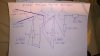
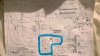
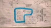
Dear all, hope you are all well, please could you lend me a hand with reading this schematic, I have highlighted the section in question on the photo of the schematic and I have also done a very crude drawing of how I have read it, would someone be able to tell me if I am correct or not and better still if someone had a lot of time on their hands would it be possible to do a quick sketch of the components in their proper order, like I say it is only the highlighted section in red and the components that I have drawn that are in question.

Thanks so much in advance. Ian
 

Attachments

  • WP_20171129_004.jpg
    WP_20171129_004.jpg
    1.3 MB · Views: 116
  • WP_20171129_006.jpg
    WP_20171129_006.jpg
    1.7 MB · Views: 121
  • WP_20171129_007.jpg
    WP_20171129_007.jpg
    1.5 MB · Views: 111
What you've drawn looks right. You need to connect all the of the negative terminals of all the capacitors together, and to the negative of the bridge rectifier. That has also to be connected to all of the points with the ground symbol.
 
Thanks very much, I just thought it odd that there would be two sets of 1K resistors both coming out the 220uf capacitor
 
Thanks very much, I just thought it odd that there would be two sets of 1K resistors both coming out the 220uf capacitor
Probably due to parts availability to get the required power since 5W resistors are a lot easier to find than 10W resistors.
 
The circuit makes sense. There is one power supply, provide by the transformer, rectifier, smoothing capacitors and resistors, ending at the 220 μF capacitor. That feeds the two anodes, one for each channel, and some additional filtering is done separately for each channel to stop one channel affecting the other.
 
Status
Not open for further replies.

New Articles From Microcontroller Tips

Back
Top