If let say now I will go on with the PIC..I wanna know the PIC can be used to store data?And when I need to retrieve it, what changes I need to do.
Another question just for knowledge.,we know that in the flash, we need the timing to do all the process and the timing is created using CPU or microprocessor...Is it we have other way to create the timing if we are not using the flash memory together with the CPU and microprocessor?
Another question just for knowledge.,we know that in the flash, we need the timing to do all the process and the timing is created using CPU or microprocessor...Is it we have other way to create the timing if we are not using the flash memory together with the CPU and microprocessor?
")
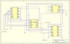
 is me again.. OK..Now I am using the :arrow: PIC16F84 for my storage of my project. So, now, my idea is to store the ID Address of the devices. Each address will only take up 3 bits. So, I am thinking of using the PORT A of the PIC as the output to the comparator to compare with the address sent out from the decoder. If the address matchm then it will trigger the device on. If it is not, the device will not turn on. If the user tends to modify the address of the device, a command bit will send out so that the previous address of the device will be overwritten with the new one.