Continue to Site

Welcome to our site!

Electro Tech is an online community (with over 170,000 members) who enjoy talking about and building electronic circuits, projects and gadgets. To participate you need to register. Registration is free. Click here to register now.

  • Welcome to our site! Electro Tech is an online community (with over 170,000 members) who enjoy talking about and building electronic circuits, projects and gadgets. To participate you need to register. Registration is free. Click here to register now.

Insulation meter test. Is it OK?

Status
Not open for further replies.

Elerion

Member
Hi everyone.
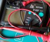
I got a new cheap 9-v powered insulation meter (250-1000V), just to see how it works, and if it fits my needs. I never used one before. I did a couple of test, and I wanted to share them, and also ask if you think the results are to be expected.

The meter works fine when measuring high value resistors (1-10 Meg).
But then I tested the insulation of several differents wires and crocodile probes (which are rated 30 Vdc) by probing the insulation and the inner conductor, and even when setting the meter to 1000 V test voltage, I get perfect insulation reading ( resistance > 2 Gohm). I did the same with some connectors (rated for low voltage too, < 60 Vdc), and I always get overload/overflow reading (so, higher than 2 Gohm).

Is this ok? Maybe I'm doing something wrong?
I thought about using the meter to test if some unknown wire, switch or connectors could be used in moderate/high voltage circuits (150-350 Vdc).

Thanks.
 

Attachments

  • ins_meter.jpg
    ins_meter.jpg
    610.8 KB · Views: 237
That's not what insulation testers are for - the low voltage rating is a GUARANTEED minimum voltage rating, surviving a short term 1000V test doesn't mean it's suitable for higher voltage use.

Insulation testers are basically for testing insulation on appliances, looking for leakage in the insulation in a transformer or motor etc.

You should also be aware that spurious leakage reasons are common place, with mains interference and safety components commonly failing high voltage testing.

So you need to pick your components base on the manufacturers specifications, not on some meaningless test - as far as wires go, it's usually pretty obvious if wires are OK for high voltages.
 
High voltage and insulation: Probably 100V wire will pass your 1000V test. But putting 1000V on that insulation for a year will cause the insulation to breakdown. A connector will pass your test, but let the part get damp or dirty or old and it may not.
 
What Ron said ^^

In addition to that, for high voltage there are creep and strike considerations, that usually occur over longer periods of time and are influenced by environmental conditions. Although those are more in the realm of hi-pot testing.
 
looking for leakage in the insulation in a transformer

Thanks for the clarification.
I thought that if it was able to detect leakage in the insulation of a transformer, it would probably detect the maximun voltage that other insulations could hold before letting some current pass through. That's leakage too, isn't it?
So, meters like this cannot be used either to test if the insulation of a transfomer is strong enough for the working voltage, just defects on the insulation, due to some areas not properly covered by it, maybe? Did I get it right?

I also suspected, but wasn't sure about the facts that schmitt trigger and ronsimpson pointed out. So thank you guys.
 
So, meters like this cannot be used either to test if the insulation of a transfomer is strong enough for the working voltage, just defects on the insulation, due to some areas not properly covered by it, maybe? Did I get it right?

Essentially to test insulation you apply a higher voltage - if it passes a short term test at 1000V then it's obviously fine for use at 240V, or the <60V you mentioned. There's no point testing at the specified usage, as it puts no strain on the insulation.

Incidentally, historically 500V was the test voltage - obtained from hand wound Megger testers :D

Likewise for earth testing, a PAT (Portable Appliance Tester) applies a high voltage for insulation testing, and a high current through the earth pin of the plug to the body of the appliance, again you use a high current to 'strain' the connection - if the earth lead was only hanging on by a thread, it would test OK for low resistance, but the high current would blow just like a fuse, making it fail the test.
 
That is correct. One is looking for insulation defects.

Wouldn't just a regular ohmeter work then?

This week I used the insulation meter to test some transformers, which are perfect.
But, in cases where the insulation is not applied correctly, the ohmeter detects it too.

There's no point testing at the specified usage, as it puts no strain on the insulation.

I understand. Thanks for the clarification.

if it passes a short term test at 1000V then it's obviously fine for use at 240V, or the <60V you mentioned.

Do you mean that if 1000V test is OK, it is safe to work with 240V on a long term?
 
Cable voltage ratings allow for conditions in the expected type of use.

Low voltage rated wires and cables have thinner insulation that's more easily damaged and provides less physical protection.
eg. typical telephone, burglar alarm or network cable - all nominal low voltage types - have insulation so thin you can split it by scratching it or just pulling hard on the cable. That could be lethal if it was carrying a high voltage.

A cable type rated for 120V or 240V use has much more rugged insulation that can stand long term use without it being likely to be damaged and expose a conductor in that normal use, over its expected lifetime.

Some types are in between - we use some multi-way cables in machine tools that are rated for 600V or higher and fine for running anything up to 415V motors etc., but are not permitted to be used "loose" or as flex for appliances and such - it can only be used it trunking, conduit or some other protected situation if it's carrying a hazardous voltage.


On another high-voltage testing subject, one thing I see fairly often are big DC motors. The carbon brushes wear in those over time and the carbon dust gets deposited all over the insulator surfaces. It it build up too much it can result in a flashover, possibly damaging the drive gear that runs the motor.

An insulation test with a contaminated motor shows the resistance getting lower as you increase the test voltage, rather than staying the same or slowly increasing, as it may do if due to eg. a trace of condensation.

High voltage testers also often have a low resistance range - that's useful for testing AC motor stator resistance for faultfinding, plus testing armatures directly segment-to-segment at the commutator when looking for shorted or open windings.
A big motor typically shows as a dead short on a normal multimeter..
 
I see that many people use these meters with DC motors, and I understand a little bit better why.

I've been using it to test EI transformer laminations.
I insulate the bolts, and it helped me to know weather there's conduction between the bolt and the laminations.
At 250 VDC, it showed a perfect insulation, but at 500 VDC one of them produced small sparks in the point of contact with the probe.
I improved the insulation. No more sparks, but at 500 VDC I got 1.000 Mohm. At 1000 VDC, there were sparks again.
Not sure if this was good enough, I improved once more. I got perfect insulation at 500 VDC now.

EI laminations are supposed to be insulated on one side. But sometimes, depending on where I probe, I get just a few megaohm resistance. Is this OK to prevent Eddy currents?

Fianlly, is it safe when there're smalls sparks when measuring? I try to take no more than one second.
 
Status
Not open for further replies.

Latest threads

New Articles From Microcontroller Tips

Back
Top