I am still struggling with with AD623 instrument amplifier a little.
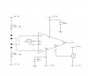
In my circuit each input (2+3) is connected to a testpin, which is of course open if not in use (there is a 4K7 in front of each input as protection). The circuit works fine when in use, but when not in use the open pins catch lots of noise and I get an erratic output signal.
How do I tie the inputs down?
The input signal is in the upper µV range, or in other words, I want to measure the voltage drop on a very low mOhm range.