Hi all,
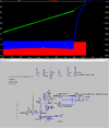
I've designed and simulated a buck circuit which tracks input current by way of a variable voltage reference, in this case it's set to around 500mA. It uses a high-side INA199 (which I simulated using components as the build in symbol doesn't work for it for some reason), and MCU logic to present a 500KHz PWM where the duty is controlled by the INA199 presenting a fault, which is latched with an auto reset. Buck controllers generally refer to this as 'hiccuping'.
The power goes into super-capacitors with an OVLO also shutting off the PWM. The inductor has been chosen to suit the frequency and input voltage range.
The logic will be MCU based and implemented in hardware where the fault is async triggered. As such the bandwidth here will be much higher than the 500KHz signal that it generates. As the current control is dependant on the impedance of the input source there will be another loop monitoring the current value and moving the reference point to settle the current around the ideal point.
The buck controller is rated to 1MHz, so this is the ceiling. I have plenty of space for a large inductor and feel 500KHz is a good target.
Running the simulation I get current control of between 440-510mA, so delta 70mA. I'm looking at whether I can optimise further. As I understand it the core restriction is going to be with the bandwidth of the current sense op-amp. I've used a 100m resistor and the lowest gain (x50) INA199 here but the LM324 is likely not accurate. According to the datasheet the INA199 only has a bandwidth of 80KHz while an alternative, INA139 is 440KHz.
Am I correct in my analysis?
The other question is whether hiccuping is the right way to go. If I instead used some form of method to turn a reference voltage and the current sense output into a variable duty PWM at set frequency that could be a tighter way to do it. Any ideas on how to do that warmly appreciated as I'm unsure where to start with it.
(Circuit uses generic components, can open and run it)