Continue to Site

Welcome to our site!

Electro Tech is an online community (with over 170,000 members) who enjoy talking about and building electronic circuits, projects and gadgets. To participate you need to register. Registration is free. Click here to register now.

  • Welcome to our site! Electro Tech is an online community (with over 170,000 members) who enjoy talking about and building electronic circuits, projects and gadgets. To participate you need to register. Registration is free. Click here to register now.

Infrared Transmitter and Receiver help

Status
Not open for further replies.
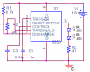
We are still having problems with our circuit. I have replaced the 555 timer that generates the 30 Khz signal. The only other thing I can think of is we are using a TIS98 transistor instead of the proposed BC337.

Could this be a problem?

At this time we will continue with this design, but if we continue to fail we will need to look into another design or place to by such devices.

Does anyone know a cheap part or product that we could buy? Details are:
We need to have a transmitter and one or more receivers that will be mounted on the robot in order to see which direction to turn. In short, the robot must follow a transmitter depending on its location.
 
Maybe you connected the pins on the TIS98 transistor backwards.
 
That seemed to be yet another issue. Thanks, but we are still having problems. Seems like the receiver is seeing signal at pulses. Since we are pulsing at 3 hz would this be seen at the receiving end? or would we see a constant low (active low receiver)?

Random question... Does IR go through a thin piece of paper?

Thank you very much!
 
Seems like the receiver is seeing signal at pulses. Since we are pulsing at 3 hz would this be seen at the receiving end? or would we see a constant low (active low receiver)?
Of course the output of the receiver is pulses of your bursts of 38kHz.
Look at the datasheet.
Like I said earlier: "Simply use a dual 555 (a 556) to make bursts of pulses. Then make the decoder ignore the bursts".

Random question... Does IR go through a thin piece of paper?
Probably poorly but it depends on the paper.
 
analog ir range detector

hello friends i am designing an ir based range detector
for transmitter i have used a 555 timer based circuit wich works on 10khz
frequency .

and reciever part consist of an 10khz sallen-key high pass filter , and then an non inverting amplifier . but thae problem is this i am not getting linear output
i have a dead band of 2-3 cm just before the ir reciever , bur for higher distance it works perfectly , can u suggest my why this:confused: is happening . :confused:
You have hyjacked this thread.
Please start your own thread about your circuit.
 
please send me the working for the circuit given by you that is IR transmitter circuit.....plzzzzz ineed the working for that ckt please help me..i found my circuit in this page attached to one of the thumbnails .plzz any one help
 
Last edited:
please send me the working for the circuit given by you that is IR transmitter circuit.....plzzzzz ineed the working for that ckt please help me..i found my circuit in this page attached to one of the thumbnails .plzz any one help
What is a "working"? Do you mean a "detailed circuit description"?

The IR transmitters in this thread are just 555 oscillators. There are many tutorials on the web about the 555 oscillator.
 
yeah i need the datailed information about working of the ckt.....that ckt is in this page only ..1st page in thumb nail.....i'm not able to attach that ckt...to this message
 
Last edited:
The first thumbnail on the first page of this thread is an IR transmitter that was posted by me. It is an ordinary 555 oscillator driving two IR LEDs in series. The LED current is (12V - 2V - 2.6V)/47= 157mA.

Look at a tutorial on the web that describes how an ordinary 555 oscillator works.
 

Attachments

  • 555 driving IR LED.PNG
    555 driving IR LED.PNG
    11.3 KB · Views: 321
Hi,

you might want to try this circuit. It was designed for obstruction detection between posts of a sliding gate. (to prevent closing the gate on a car)

The number of IR-LEDs is not the most important thing concerning range.

Most IR-LEDs have an IPCE value of 0.5 to 15mW/sr. The LD274-3 has one of 80mW/sr. Fitted with a reflector the maximum range is about 15m. The max. forward current is 100mA.

The current limiting resistor is calculated for VCC=5V and maximum 50mA forward current.

The circuit as posted here has no additional circuitry for a steady low or high output. If you use an MCU you can easily calculate for two or three full cycles (of the burst control oscillator) to determine if the signal is actually high or low.

It will be steady high when the IR-beam is broken.

The oscilloscope screenshot shows the signals at 13Hz burst control frequency and 20% duty cycle.

Remark: You might connect the /Reset pin (IC2) to VCC or leave it floating. I omitted it for PCB layout considerations.

Boncuk
 

Attachments

  • IR-BARRIER-SCH.pdf
    33.7 KB · Views: 359
  • IR-TX-20.jpg
    IR-TX-20.jpg
    36.9 KB · Views: 291
Last edited:
Status
Not open for further replies.

Latest threads

New Articles From Microcontroller Tips

Back
Top