Continue to Site

Welcome to our site!

Electro Tech is an online community (with over 170,000 members) who enjoy talking about and building electronic circuits, projects and gadgets. To participate you need to register. Registration is free. Click here to register now.

  • Welcome to our site! Electro Tech is an online community (with over 170,000 members) who enjoy talking about and building electronic circuits, projects and gadgets. To participate you need to register. Registration is free. Click here to register now.

Infrared Transmitter and Receiver help

Status
Not open for further replies.

senior project

New Member
I have used several circuits found on this forum and other websites, but nothing seems to work for me. I am looking to build a circuit that will transmit and receiver an IR signal. I am new to wireless communication and especially IR. I bought an IR LED from allelectronics.com, CAT# ILED-8 and some receivers, CAT# PCM-1, CAT# IRD-11.

The receiver that I have operates at 30kHz. I need a range of 6ft. I currently have a range of 3ft, but it is very sensitive. If I get slightly of the direct line of site I am screwed.

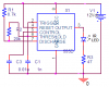
I am using a 555 timer circuit. I put 3 IR led's in series to give more range, which seemed to help a little, but not much.

I tried using RF, but bought the wrong modules and had problems with shielding.

The purpose of this part of the project is to create a robot follower. I have a robot ready to receive signal from 3 sides, left straight and right. Depending on which receiver receives the IR signal (from about 6ft away) the Hbridge will then drive the motors to turn the robot in that direction.

I have tried so many things an am currently frustrated with this part of the design. Please help.

Much Appreciation.
 
Post schematics of your circuits, particularly the 555 driving the IR LEDs.
 
Here is my circuit for the transmitter with a pspice output. The D1N4148 is the IR LED. The simple receiver circuit I used is the device itself tied to Vcc (5volts) ground and the output. Do I need a specific circuit for the receiver or is this already included in the receiver device (module)?

Thanks,
 

Attachments

  • transmitter three circuit.doc
    33 KB · Views: 1,777
Last edited:
its attached to the last reply, but here it is again.


Right, it is, but I was wondering how to model it in pspice so I used the 1N4148. In my test circuit, done in my lab, I used a couple IR LED's; allelectronics.com, CAT# ILED-8.
 

Attachments

  • transmitter three circuit.doc
    33 KB · Views: 770
Last edited:
You connected the IR LEDs wrong so you burned them out and maybe also burned out the 555. Maybe you are lucky if the battery is dead.

If your IR receiver is an IR receiver IC then it reduces its gain if the 30kHz signal it receives is continuous and not in data bursts. Look at its datasheet.
 
Oh I see yeah the circuit does show it backwards, but I did connect it correctly. I will double check. How would I go about making something that is not continuous? using the 555 timer? I noticed that if I move the transmitter around the receiver will get the signal, but then stop. This must be what you were saying about the receiver dropping the gain.

I have the datasheet attached. Are there receivers that allow continuous signal?

The purpose of the IR link is to have a transmitter always transmitting IR then received by several IR Receivers to determine location.
 

Attachments

  • receiver datasheet.pdf
    179.9 KB · Views: 1,408
Last edited:
Oh I see yeah the circuit does show it backwards, but I did connect it correctly.
The resistor is in the wrong place.
The IR LED has a max allowed continuous current rating of 100mA or 200mA for very short pulses.
But the max allowed output high current of the 555 is 200mA and it will try to supply 1A to blow itself up and also blow up the LED. The 47 ohm resistor adds even more current to the LED.

When the 555 tries to go low then the 47 ohm resistor will have a current of more than 200mA and will also blow up the 555.

The 555 can drive the LED when the 47 ohm resistor is in series with the output of the 555 and the LED.
 
Last edited:
Are there receivers that allow continuous signal?
I don't think so. They reduce the gain during continuous 38kHz IR pulses because of interference from compact fluorescent light bulbs that produce 38kHz IR pulses continuously.
Simply use a dual 555 (a 556) to make bursts of pulses. Then make the decoder ignore the bursts.

Here is my fix to your tx schematic:
 

Attachments

  • 555 driving IR LED.PNG
    555 driving IR LED.PNG
    11.2 KB · Views: 1,345
I tried the revised transmitter circuit and the 47 ohm resistor is really hot!

I also dont quite understand your last response when mentioning the decoder ignoring the bursts. Can I make a circuit to generate a 30khz signal via 555 timer then a 3hz pulse via the second 555 timer? Wouldn't this still be considered a continuous signal?
 
I tried the revised transmitter circuit and the 47 ohm resistor is really hot!
Maybe the IR LEDs are burnt out and are shorted?

Didn't you calculate the power dissipation then use a resistor size that can handle the heat?
12V supply. Two 1.3V IR LEDs. 10V max high output voltage from the 555.
Then the 47 ohm resistor has 7.4V across it and its pulsed current is 157mA. The current is turned off for half the time so is an average of 79mA. Then the average dissipation is 292mW. A quarter-watt resistor will be smoking and a 1/2W resistor will be pretty darn hot.

I also dont quite understand your last response when mentioning the decoder ignoring the bursts. Can I make a circuit to generate a 30khz signal via 555 timer then a 3hz pulse via the second 555 timer? Wouldn't this still be considered a continuous signal?
The datasheet for the receiver explains the number of pulses in a burst and the number of pulses for the pause between bursts.
 
The quarter watt resistor was the problem, don't know how I missed that.

My new plan is to use the attached schematics. The first schematic ("IR Transmitter.GIF") is the 555 timers, and the second schematic ("IR-TX.gif") is the IR LED, without the 555 timer shown in that schematic. I'm connecting the 2 to create the 30 kHz pulses at 3 Hz bursts, and then have a variable gain to the IR LED. I found these schematics on another thread.

Thanks for all of your help.
 

Attachments

  • IR Transmitter.GIF
    IR Transmitter.GIF
    8.1 KB · Views: 815
  • IR-TX.gif
    IR-TX.gif
    10.1 KB · Views: 694
  • receiver datasheet.pdf
    179.9 KB · Views: 617
Well Thanks for all your help and the help from others. I really appreciate it. I will give this circuit a try sometime soon and get back to you with an update.
 
Sorry for the late response, but due to finals, work, a friends funeral I have had a hard time finding time to post and test the circuit.

I have the circuit hooked up as I type and seem to be unable to receive anything. I checked the connections and found nothing wrong with the way the schematic shows the connections. When I used one 555 timer to generate a 30khz signal I would receive signal, but not all the time and only about 3 ft away.
 
Ok. I found one problem. I had pin 3 grounded on the pulse 555 timer feeding the transistor. Now I measured the current going into the transistor to be 1mA. The current out is around 5mA, not enough drive IR.

The voltage across the IR LED is 1.2Volts each, since I have 2 in series there is 1.2 V across each making 2.4 across both IR LED's.

What is causing my current to be so low?

Thanks
 
Last edited:
You shorted the output of the 555 which damaged it.
Replace the 555.

With a base current of 1mA then the collector current of the transistor should be at least 20mA.
Maybe you have the transistor connected upside down. Check which pin is which on its datasheet.
 
Status
Not open for further replies.

Latest threads

New Articles From Microcontroller Tips

Back
Top