Jordan_Zillen
New Member
Hey there Guys,
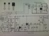
A while ago i managed to get my hands on a couple of old electronics magazines, "Electronics Africa", in it i found an on going article on how to build an infra red alarm system.(Picture attached)
Although it may be an old design, I have decided to try build this project, but have come into a few problems, and was wondering if any one could assist me? When the project is switched on, the relay is automatically triggered, therefore switching my siren on permanently(Broken beam).
I managed to get hold of most of the components listed, except for the BPW14(Photo-transistor) used in the receiver unit. My electronic outlets dont stock this item any more as it is an old component. With some digging, ive come across the newer components such as the TSOP1736, which reads a 36kHz signal... where as my circuit runs on a 1kHz signal. Now i've tried out a transmitter that sends a 36kHz signal, but this does not work? Would i need to re-design my control board to allow for the higher signal?
I've also tried using the PT202C(Photo LED), using the 1kHz signal. When using my multi-meter, i can see the transmitter communicating well with the PT202C, but still have no success in the actual circuit working. Ive checked and RE-checked all my wiring, and everything appears correct.
I dont get much of a signal out of my receiver, after passing through C3(470pF), which could be part of my problem? But also D2(IN4148) on the control board is suppose to rectify a negative voltage from C11(100nF)... which it does not do? Ive tested the diode, and it IS working.
How do i get T3 to switch on, in turn switching T4 off.... meaning an unbroken beam?
I have also made the necessary adjustments with my power supplies, to get the recommended voltages, and currents...
Please if any one can help me id be eternally grateful!!!!
thanks very much.
")
