Continue to Site

Welcome to our site!

Electro Tech is an online community (with over 170,000 members) who enjoy talking about and building electronic circuits, projects and gadgets. To participate you need to register. Registration is free. Click here to register now.

  • Welcome to our site! Electro Tech is an online community (with over 170,000 members) who enjoy talking about and building electronic circuits, projects and gadgets. To participate you need to register. Registration is free. Click here to register now.

induction heater , zvs

Status
Not open for further replies.

gdr

New Member
good afternoon to all ,

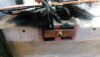
my self electrical & electronics dip .engg . Chennai native , Iam working over precious metal refining in need ti melting selected induction heater zvs irfp260n 12-24 volts , , the circuit working well , design was both mosfets fixed in separate heat sinks isolated with the metal arts , connecting 2x 12v 7.5 AH batteries the process started , when inserted pen kinfe inside red hot happened with in second s, after graphite crucible was partially inserted with in sec the both gate leads from inner doping of mosfet say blown out . fired switched off . can able to fix the problem ifeel that the mosfet leads brought out separately too heat sinks may b problem but cooling is good since the heat sinks are portable inverter mch setet up .guide me an circuit for gold melting with 35mm dia crucible if wrong correct me
 
Dear sir this is board designed by own, it is clear that the load of 35mm dia graphite curcible is it higher load for this circuit at 24 v vcc I think sir .dammaged MOSFET is als shown sir
 

Attachments

  • Screenshot_20191124-214635.png
    Screenshot_20191124-214635.png
    366.8 KB · Views: 132
  • PHOTO_20191114_085328.jpg
    PHOTO_20191114_085328.jpg
    699.5 KB · Views: 142
The other guys on this forum are smarter than me they can probably help you better. I built my induction heater 7 year ago and made improvements many times it was very helpful for me to have a 50 amp meter in the power supply circuit so I could make sure not to blow the mosfets. I changed my mosfets several times finally found 55NF06L mosfets rated 55 amps 60v with .015 ohms resistance work best for me. Do you have an LCR meter to test your coils make sure 50uh really is 50uh. The larger your work coil L3 gets the more power it takes to heat up a part. Higher frequency gives you more skin effect you need to experiment with different frequencies to find what works for your project. 200KHz makes my a 10mm steel rod heat Red hot on the outer surface while it stays cold in center. 60KHz heats my 10mm steal rod very even to the center red hot in 14 seconds. Check load KHz of L3 with a meter. My work coil is 2uh. Use online calculator to find 50uh inductive reactance value. I learned several online calculators gave me wrong information. Another thing I learned from rail gun cap bank connect mosfets to the center of our capacitors bank it makes the circuit heat parts up faster and appears to have much more power while amp meter still has the same reading. Cut #2 wire off of the mosfet use heat sink tab as #2 wire you can pull almost 2 times more power from the mosfet without blowing it up. Don't try using both #2 wire & heat sink tab it will blow the mosfet. I have a 3 ounce solid aluminum heat sink it can take 750 watts for 2 minutes before getting warm. If you want to melt metal you need higher voltage probably 100 volts DC. I left insulation on my load coil wire so not to accidently short it out and blow the mosfets. My parts get red hot in a few seconds plastic insulation never has time to get hot. Your part lay out is probably just as important at the circuit. RF voltage on my 8 turn load coil tests 90 volts AC. Make sure your resistors R1 & R2 are correct so mosfet turns completely off between cycles. Do math or use online calculator to build coils the correct value so inductive reactance gives you the correct current keep it below the mosfet rating. Amp load goes up when you put a metal part in the work coil. Make sure all 8 caps are rated 500v or higher, mine are 1000v I like things to be bullet proof if possible. Solder copper or brass plate to #10 wire to bolt your mosfets too.


100_5689.JPG


100_5678.JPG


023.JPG
 
Last edited:
Dear sir. back on an doubt. Other subject
One of my area the neutral wire end terminal of socket 1phase burnt data observed voltage ok earth to neutral 1.6 v neutral to phase 246v earth to phase 246v found the neutral socket is heating slowly burnt .idea to solve sir
 
Status
Not open for further replies.

New Articles From Microcontroller Tips

Back
Top