Plip
New Member
Dear Everyone
I breed birds of prey. We use incubators to hatch eggs under controlled conditions. Unfortunately falcon eggs are unlike chicken eggs (which seem to hatch if you shout "incubator" at them), they require a highly regulated temperature to have a decent hatchability. The incubators I use, are not really designed for use with falcon eggs, and need to be modified to be made usable as the method of control used in the incubator (a bead thermistor) is not reliable enough to provide the stable temperature needed.
To regulate the temperature, I need to use a "contact thermometer". The thermometer has two lead rings spaced about an inch apart on the thermometer which contact the mercury as it rises. The usual way to use a contact thermometer is via a mechanical relay (double pole), the contact thermometer being connected in series to the coil of the relay so that when the mercury rises, a contact is made which draws current through the coil of the relay which pulls the contacts and switches the main voltage to the incubator heating coil.
However, I and many other breeders have found that using mechanical relays is very troublesome, the relays either switching violently back and forth or the contacts welding together completely, effectively removing the thermometer control with the result of uncontrolled heating of the incubator and subsequent cooking the eggs...
A solid-state relay is far more reliable. My father many years ago found an electrician who made him two which gave perfect service. However, I have been having trouble finding anyone who can help me with this. In one store I went to I was sold an OAC5 relay which, I was informed would work just fine. Maybe I didn't explain myself properly, but the problem is that the 110V side of the relay is switched on only when there is charge flowing through the switching side, but in my case I need the 110V to be switched on when there is no charge flowing through the switching side, i.e. the temperature in the incubator is dropping therefore the mercury in the thermometer descends and disconnects the circuit, this is when I need the heating coil to be switched on so that the temperature will again rise.
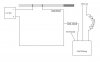
I tried, using my distant memory of high school electronics, to design a relay circuit incorporating the OAC5 relay I had bought, on the principle (hope) that electricity will always flow through the easiest route.... unfortunately it didn't work. I attached the circuit diagram as a .jpg file.
If someone could help me design a circuit I would be very grateful.
The amount of charge flowing through the thermometer has to be limited to under 20mA, (the manufacturer recommends 3mA but the thermometer will withstand more). The incubator heating coil runs at 110V and draws 1.7A.
I apologize if my explanations seem over simplified or lengthy.
Thanks in advance!
I breed birds of prey. We use incubators to hatch eggs under controlled conditions. Unfortunately falcon eggs are unlike chicken eggs (which seem to hatch if you shout "incubator" at them), they require a highly regulated temperature to have a decent hatchability. The incubators I use, are not really designed for use with falcon eggs, and need to be modified to be made usable as the method of control used in the incubator (a bead thermistor) is not reliable enough to provide the stable temperature needed.
To regulate the temperature, I need to use a "contact thermometer". The thermometer has two lead rings spaced about an inch apart on the thermometer which contact the mercury as it rises. The usual way to use a contact thermometer is via a mechanical relay (double pole), the contact thermometer being connected in series to the coil of the relay so that when the mercury rises, a contact is made which draws current through the coil of the relay which pulls the contacts and switches the main voltage to the incubator heating coil.
However, I and many other breeders have found that using mechanical relays is very troublesome, the relays either switching violently back and forth or the contacts welding together completely, effectively removing the thermometer control with the result of uncontrolled heating of the incubator and subsequent cooking the eggs...
A solid-state relay is far more reliable. My father many years ago found an electrician who made him two which gave perfect service. However, I have been having trouble finding anyone who can help me with this. In one store I went to I was sold an OAC5 relay which, I was informed would work just fine. Maybe I didn't explain myself properly, but the problem is that the 110V side of the relay is switched on only when there is charge flowing through the switching side, but in my case I need the 110V to be switched on when there is no charge flowing through the switching side, i.e. the temperature in the incubator is dropping therefore the mercury in the thermometer descends and disconnects the circuit, this is when I need the heating coil to be switched on so that the temperature will again rise.
I tried, using my distant memory of high school electronics, to design a relay circuit incorporating the OAC5 relay I had bought, on the principle (hope) that electricity will always flow through the easiest route.... unfortunately it didn't work. I attached the circuit diagram as a .jpg file.
If someone could help me design a circuit I would be very grateful.
The amount of charge flowing through the thermometer has to be limited to under 20mA, (the manufacturer recommends 3mA but the thermometer will withstand more). The incubator heating coil runs at 110V and draws 1.7A.
I apologize if my explanations seem over simplified or lengthy.
Thanks in advance!