Continue to Site

Welcome to our site!

Electro Tech is an online community (with over 170,000 members) who enjoy talking about and building electronic circuits, projects and gadgets. To participate you need to register. Registration is free. Click here to register now.

  • Welcome to our site! Electro Tech is an online community (with over 170,000 members) who enjoy talking about and building electronic circuits, projects and gadgets. To participate you need to register. Registration is free. Click here to register now.

incremental conductance algorithm for MPPT

Status
Not open for further replies.

PG1995

Active Member
Hi,

I was reading on incremental conductance technique to locate maximum power point for a solar panel.

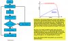
What is "C" in this flowchart for incremental conductance algorithm? The "C" is also mentioned for perturb and observe algorithm flowchart on page #14. Could you please help me with this? Thank you!

[Reference: https://www.slideshare.net/manish_barthwal/seminar-report-on-mppt]
 

Attachments

  • inc_con.jpg
    inc_con.jpg
    36.6 KB · Views: 286
Thank you!

That's what I suspected but what puzzled me more was the reason for using letter "C".
 
Hi again,

Could you please help me with this question about three-point weight Perturb and Observe method?

Please have a look here.

You can see that power at B is greater than A and power at C is less than at A. In this case you would decrease duty cycle to keep on moving toward maximum power point which is the knee point. Do you agree?

I'm going to assume you agree with what I said above. Please have a look on the highlighted text. To me it seems like a contradiction, the duty cycle should instead be decreased. Do I have it right?

[Reference: https://drive.google.com/open?id=1ChRuQNzAKw1PGIwG-Whx2c5nfSZDCp8c]
 

Attachments

  • three_point_average_1.jpg
    three_point_average_1.jpg
    507.6 KB · Views: 255
If the power is too high draw more power from the array. That will make V lower.

If there is no power from the array you get an output of Voc. If your shorted, the voltage output will in the limit approach zero.

Now wrap you head around what duty cycle. It's like the wrong variable used for understanding.

You can't really do a set V, measure I, type of thing.
 
Last edited:
Yes its an error . two +slope measurements in P indicates reducing current with duty cycle will raise P in the +ve slope direction.

Whereas in the VI curve computing I/V must match ΔI/ΔV or even V/I must match ΔV/ΔI same thing , at MPPT. This means the MPPT regulator matches its input impedance or conductance to the PV source for Max Power Transfer.
 
Thank you.

Please have a look here.

It looks like I was wrong. Please have a look on the perturb and observe algorithm flowchart on the left. It says that when power increases, increase the duty cycle. This statement is saying the same thing as that 'contradictory' statement, "Of the three measured points, if two are positively weighted, the duty cycle of the converter should be increased" from post #4.

But why is so? When an MPPT system starts, the panel voltage is going to be Voc. So, the system starts its journey toward the maximum power point from the left, i.e. from point Voc. Though it seems natural to assume that the system moves from right, i.e. 0 V, towatd the left, it's wrong.

Even in the reference PDF from post #4, you can see the same flowchart. Thank you!
 

Attachments

  • p&o1.jpg
    p&o1.jpg
    187 KB · Views: 150
Your problem is due to the flowchart only taking into account the direction of measured power change. It must also take into account the last direction of duty cycle change, this allows discrimination of whether you are on the right or left side of mpp and in fact reverses the sign of duty cycle change with respect to power change accordingly :) I have implemented this algorithm myself and my house runs on the result!
 
Thank you!

Your problem is due to the flowchart only taking into account the direction of measured power change. It must also take into account the last direction of duty cycle change, this allows discrimination of whether you are on the right or left side of mpp and in fact reverses the sign of duty cycle change with respect to power change accordingly :) I have implemented this algorithm myself and my house runs on the result!

I agree with you but it's just a flowchart to give you an overall feel of how the algorithm works. Mostly, if not always, this is how a flowchart for perturb and observe algorithm is shown.

Anyway, in the code you can easily reverse the direction of duty cycle as is shown below.
mppt_duty-jpg.117208


By the way, did you make your system yourself? I'm asking you this because I can use your help in this regards. I also have an experience with this system so was just trying to expand my knowledge about it. Thanks a lot.

PS: fourtytwo I think this flowchart for perturb and observe algorithm is more close to what you were suggesting. [Reference: https://drive.google.com/open?id=1hAZA3-larteGFX8-FlZ5M6d-QH6Zmf2W (page #6)]
 

Attachments

  • mppt_duty.jpg
    mppt_duty.jpg
    37.6 KB · Views: 229
  • perturbANDobserve1.jpg
    perturbANDobserve1.jpg
    34.6 KB · Views: 247
Last edited:
Thank you!
I agree with you but it's just a flowchart to give you an overall feel of how the algorithm works. Mostly, if not always, this is how a flowchart for perturb and observe algorithm is shown.

Then why did you post an incorrect flow chart and ask everybody what was wrong with it if you already knew ?

As for your revised chart I see it uses voltage change to determine direction, as I stated I prefer to use duty cycle change as it is stable.

That code snippet seems completely irrelevant as it is apparently based on your erroneous flow chart!

Yes I made my system myself and as you will find out in practice the detail of the problem is much greater in order to be able to operate successfully across the entire insolation range, but it is far better to build a prototype based on the principles you have so far discovered and learn the rest by experience :)
 
Thank you.

Then why did you post an incorrect flow chart and ask everybody what was wrong with it if you already knew ?

I only found the given flowchart after your reply and then shared with you to let you know that I was wrong and in hope that someone else stumbling upon the thread could benefit from it.

That code snippet seems completely irrelevant as it is apparently based on your erroneous flow chart!

That code might be irrelevant to the discussion but it's a good code and not based on that flowchart. It just reverses the 'direction' of duty cycle based on power difference.

Yes I made my system myself and as you will find out in practice the detail of the problem is much greater in order to be able to operate successfully across the entire insolation range, but it is far better to build a prototype based on the principles you have so far discovered and learn the rest by experience :)

I already built a working prototype more than a year ago.

Best wishes,
PG
 
Last edited:
Status
Not open for further replies.

Latest threads

New Articles From Microcontroller Tips

Back
Top