Continue to Site

Welcome to our site!

Electro Tech is an online community (with over 170,000 members) who enjoy talking about and building electronic circuits, projects and gadgets. To participate you need to register. Registration is free. Click here to register now.

  • Welcome to our site! Electro Tech is an online community (with over 170,000 members) who enjoy talking about and building electronic circuits, projects and gadgets. To participate you need to register. Registration is free. Click here to register now.

Increase efficiency

Status
Not open for further replies.

mading2018

Member
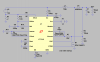
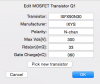
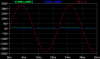
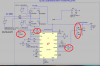
Do anyone have any suggestion how I can increase the efficiency for the LT1248 in LTspice? I have tried to change many parameters (the red circles) in the circuit according to the Data sheet, but it seems that nothing helps.. I always obtain the same output, about 500 W.

--edit--
Is it possible to use a correction factor otherwise if it not possible to increase the efficiency?
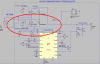
Cause I know from theory that the totem-pole should have higher efficiency than boost.
 

Attachments

  • totem_increase output power?.png
    totem_increase output power?.png
    122.1 KB · Views: 337
  • TOTEM_ACDC_PFC_LT1248 dflipflop NEW.asc
    6.5 KB · Views: 172
Last edited:
The red circles are critical to the workings of the IC. Don't play with them unless you know what they do.
If your total power is 500w and you change a part that has 0.5 watts in it there is little effect. You should look for a part(s) that have many watts loss in them.
Why is "Iac" connected to "OUT". In real life this will kill the IC. C3 will also die.
L12: in real life will be hot. You probably have the a theoretical coil so there is no loss.
Q1, Q2, D1, D3 are where you are loosing power. There are two typed of power loss.
DC: is RDCon of Q1,2 and current
AC: loss from the switching edges.
 
The red circles are critical to the workings of the IC. Don't play with them unless you know what they do.
Okay, I will leave them.

Why is "Iac" connected to "OUT". In real life this will kill the IC. C3 will also die.
I followed one of the demo circuits, so thats why it was connected to OUT. But I can test to disconnect Iac from OUT. See the attached file.

L12: in real life will be hot. You probably have the a theoretical coil so there is no loss.
Yes, it is a theoretical coil.

DC: is RDCon of Q1,2 and current
Hmm, I am not sure what do you mean with RDCon? You mean residual-current device?
 

Attachments

  • Capture.PNG
    Capture.PNG
    49.3 KB · Views: 190
The MOSFETs that you chose, when on, have a resistance of about 0.2 ohms.
Resistance Drain-Source On RDS on
So you can get the watts loss (at DC) from knowing the resistance and current.
In your case the AC power loss is much higher.
 
to avoid too high losses in AC?
AC loss is related to how fast the MOSFET turns on and off. How you drive the Gate voltage. How much internal capacitance inside the MOSFET.
AC loss is not directly related to RDSon but indirectly related.
 
So it should be a higher value of RDS on to avoid too high losses in AC?
If I understand Ron's point correctly, then no. You want Rdson to be as low as possible.

In a non-ideal PFC circuit, the majority of the heat is in the power semiconductors and the boost inductor. The main way to reduce heat in either one is to oversize them. For the inductor it is simple; fatter wire means lower resistance. Optimizing the core material for the frequencies of interest helps, but the wire is the thing. For the FETs it is a bit more complicated, because larger FETs have larger gate capacitance. So it is a tradeoff between power loss in the on resistance, and energy pumped into and out of the gate on each cycle.

Working from memory, I think there was a 2nd gen PFC controller from Unitrode in the 90's that recovered the reverse recovery energy in the boost diode into an extra, smaller inductor that then discharged back to the input, or something like that.

ak
 
I selected this MOSFET, it has low RDSon and high internal capacitance. However, it seems there is no change in the output.
If I compared with the original demo model, where I changed the DC source to AC source like my case, it succeeded to obtain higher output.

I guess it is because of my MOSFETs in the bridge as you have describe it.

recovered the reverse recovery energy in the boost diode into an extra, smaller inductor that then discharged back to the input,
It seems good if it works. Could you please show how it would like for my circuit? Not sure where the connections should be exactly.
 

Attachments

  • Rdson.png
    Rdson.png
    31.8 KB · Views: 183
  • TOTEM_ACDC_PFC_LT1248 dflipflop NEW NEWER.asc
    6.3 KB · Views: 169
  • wave.PNG
    wave.PNG
    22.4 KB · Views: 175
  • LT1248 demo.asc
    4.2 KB · Views: 176
Do you have a source for the circuit you are using? That is not a traditional boost PFC stage.

ak
 
Do you have a source for the circuit you are using? That is not a traditional boost PFC stage.
There is no IC I know of that will do this job. Nothing from Linear.com.

I think there is 0.8 volts less loss in the diodes. (less diodes) But the cost is two MOSFETs and a top side gate driver. (and a IC that does not exist)
 
The gate drive does nothing but continuously set a flipflop. The MOSFET gate drive voltages reference the Q output (maybe), but ont schematic it looks like Q is DC. I sorta kinda see how the input might work, but I don't see any advantage over the datasheet circuit.

ak
 
The Iac pin on the LT1248 needs to see the rectified, unfiltered, AC input. You've got it directly connected to the boosted, fitered, DC rail.

Without seeing the AC voltage waveform, the LT1248 won't be able to create the varying pulse width modulation on the GTDR pin necessary to produce the PFC function.
 
The Iac pin on the LT1248 needs to see the rectified, unfiltered, AC input.
Yes.
If the 1meg resistor was put back in, there is no "rectified unfiltered AC input". So the IC can not see the voltage from the power line.
 
The Iac pin on the LT1248 needs to see the rectified, unfiltered, AC input. You've got it directly connected to the boosted, fitered, DC rail.

Without seeing the AC voltage waveform, the LT1248 won't be able to create the varying pulse width modulation on the GTDR pin necessary to produce the PFC function.

Ah, I see. Yeah, it makes sense. You mean like this, see the attached image.
Hmm, it seems however, there is no difference in the output?
 

Attachments

  • TOTEM_ACDC_PFC_LT1248 dflipflop NEW NEWER.asc
    6.5 KB · Views: 156
  • Iac.png
    Iac.png
    109.7 KB · Views: 174
The gate drive does nothing but continuously set a flipflop. The MOSFET gate drive voltages reference the Q output (maybe), but ont schematic it looks like Q is DC. I sorta kinda see how the input might work, but I don't see any advantage over the datasheet circuit.
The problem is that there is no IC component that is existing for a totem-pole configuration. So I tried to replicate the pulse sequence according to this source (where Q3 and Q4 is not included in my topology according to another source, its a bridgeless totem-pole PFC).
Hmm, yeah, would it be more accurate to use GTDR directly to the mosfets instead? or should I try to find another IC? I use LT1248, cause here I can set the switching frequency and it can obtain a output power up to 1500 W.
 

Attachments

  • TOTEMPOLECHARACT.pdf
    100.3 KB · Views: 206
  • Waveform.png
    Waveform.png
    64.5 KB · Views: 183
  • totemPFCin.png
    totemPFCin.png
    40 KB · Views: 173
Last edited:
The app note you just posted makes it very clear that
1. The chip you are using cannot perform this function.
2. As of one year ago, there are *no* control chips that can.
3. The timing of the FET drives is "very complex".

Why not start with the traditional circuit in the datasheet and see if it works for you?

ak
I have already done that, I have made a boost PFC topology to work. But for my second topology, it has to be totem-pole (since the school wants to have it)..
Can I use a correction factor otherwise? just to compensate for the low efficiency or something.
 
Last edited:
Status
Not open for further replies.

Latest threads

New Articles From Microcontroller Tips

Back
Top