Continue to Site

Welcome to our site!

Electro Tech is an online community (with over 170,000 members) who enjoy talking about and building electronic circuits, projects and gadgets. To participate you need to register. Registration is free. Click here to register now.

  • Welcome to our site! Electro Tech is an online community (with over 170,000 members) who enjoy talking about and building electronic circuits, projects and gadgets. To participate you need to register. Registration is free. Click here to register now.

INA219 Power monitor- Making floating voltage measurement to zero

Status
Not open for further replies.

Wond3rboy

Member
Hello

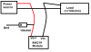
I am working a simple power monitor that uses an Arduino and an INA219 power monitor. The current part is pretty straight forward. However, (understandably) when I leave the the line floating, the bus and shunt voltage readings provide the supply voltage. I wanted to know what are the ways I can get over it. Currently my noob sense of electronics design suggests that connect a pull down resistor of say 10kΩ. However, that might have an effect on my current measurement. Is there a better way to get rid of the floating non-zero voltage reading?

Thanks.
 
A schematic will help. (worth a 1000 words)
The 10k resistor will connect to ground on one end.
The other end could connect to either end of the current shunt resistor. One end will add some current to the current reading, but the other end will not add current.
I will draw a schematic if you want.
 
Hello Ron

Thanks for the reply. I have made a pathetic schematic in paint since the connections are straightforward. The idea is to measure the voltage of the power source. The INA module is connected to the Arduino which reads it off.
 

Attachments

  • inaschematic.png
    inaschematic.png
    8.8 KB · Views: 242
I think the bottom wire from "Power Source" to "Load" should be "Gnd".
I like where you put the 10k resistor.
You need a resistor from "Power Source" to "Load". I drew a 1 ohm resistor. This is where the current will flow. It will make a reading of 1 volt for 1A. You can pick a different resistor.
upload_2017-4-9_11-39-51.png
 
hi,
This is the adafruit PDF, very low quality schematic.
E
 

Attachments

  • adafruit-ina219-current-sensor-breakout.pdf
    954.7 KB · Views: 261
Thanks Ron and Eric.

Ron, I believe thats the shunt resistor right? The INA219 module by Ardafruit already has a shunt resistor of 0.1Ω present.

Also, I have been thinking at dropping the voltage measurement using this module and use an analog sensor to perform voltage measurement. However, since the voltage might come to as low as 1 mV, do you suggest I stick in a INA128 (quiescent current 700μA) with sufficient gain to extract this voltage. If so, is there a straight forward way to compensate for this current thats been reduced from the taken current reading?

With the present settings, the current resolution is 0.1mA(100μA) so 700μA would be quite a large deviation.

Thanks for taking to time to reply.
 
Last edited:
quiescent current 700μA = is the current on the power supply pins of the INA219.
This current might be as high as 1mA/ typically 700uA but could be as low as (?).
If you connect the power supply pin to one side of the shunt resistor the (about) 700uA will be in the readings
BUT
Connect to the other side of the resistor will not show this extra current.
 
ACS711 is another type of device.
What current level are you looking at?
What voltage?
ina169 is another option.
 
Helo Ron

The ACS711 is available but the INA169 is not :(
The current 'range' would be in mA (since she is not an Electronics engineer) she doesn't know the exact value.

The problem is with the voltage, before I was told it would be around 5V (for which the pull-down resistor thing was working fine). Now, I have been asked to make modifications to make it capable of measuring 2.8mV.

The way I am looking at things, it might require a non-linear amplifier (anti-logarithmic) that emphasizes more on the lower end voltages and leaves the top end more or less the same as the Arduinos supply is 5V. I am also looking at getting an external ADC (a 16-bit one) and just reading the amplified output off as a simple voltage and rescaling it in the Arduino.

I think thats too much for an Arduino based DIY measurement unit. Maybe I suggest to her to buy something commercial.

I have to do all this while being severely limited with the components I can get locally.
 
I have not had good luck with stable "anti-logarithmic" amps.
Some ADCs have a gain amp inside. Set the gain to 1 for high voltage and to 2, or 4 for low voltage measurements. (probably can't get the parts)
I would look at 16 bit. The small ones are slow.
 
Hi Ron

Oh! I think I will do the gain amp ADCs. I have come across a few modules that I can use. Will need to get these shipped though this is going to put me off my schedule since I can only afford local post.

Thanks for your help and insight in to this. Have a nice day!
 
Status
Not open for further replies.

Latest threads

New Articles From Microcontroller Tips

Back
Top