Continue to Site

Welcome to our site!

Electro Tech is an online community (with over 170,000 members) who enjoy talking about and building electronic circuits, projects and gadgets. To participate you need to register. Registration is free. Click here to register now.

  • Welcome to our site! Electro Tech is an online community (with over 170,000 members) who enjoy talking about and building electronic circuits, projects and gadgets. To participate you need to register. Registration is free. Click here to register now.

implementation of a CdS cell optical Encoder for Treads

Status
Not open for further replies.

Krumlink

New Member
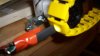
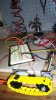
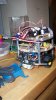
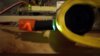
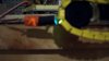
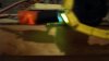
Currently I am working on perfecting a CdS cell optical encoder for tank treads. Tank treads can be difficult to work with sometimes, but I have found a way to use the gaps between the treads and a simple voltage divider using a CdS cell with a White LED to "flood" the tread piece and have the CdS cell to read the corresponding brightness. when the tread rotates to the joint, most of the light is sent inbetween and hits the idler cog, creating a dimmed effect. This can easily be seen by the "flashing" or "strobe" effect of the reflection. This will be better explained once it is complete.
 
Explanation seemed fine to me. Wouldn't dirt/debris be a problem though or is this an indoor robot? I think you might have problems with this in practice though as ambient light is gonna screw with it pretty bad. Why not do a simple rotary encoder on the wheel the drives the tread? I've always liked the look and multi terrain ability of treads but from a control standpoint they're a pain in the arse because you have to acount for slippage.
 
Explanation seemed fine to me. Wouldn't dirt/debris be a problem though or is this an indoor robot? I think you might have problems with this in practice though as ambient light is gonna screw with it pretty bad. Why not do a simple rotary encoder on the wheel the drives the tread? I've always liked the look and multi terrain ability of treads but from a control standpoint they're a pain in the arse because you have to acount for slippage.

This will be for an indoor robot, and since there are large gaps between tread pieces, and there are few false detects, and the reference voltage can be adjusted to reduce false detects. As for ambient light, I used 5000mcd white leds to help blast each tread with a ridiculous amount of light to remove any possibility of ambient light reducing the effectiveness of each tread. Accuracy is best when it is within 3/4'' of the tread.
 
Is it really advantageous over a rotary encoder on one of the driving wheels? Seems more complex in general which means more prone to error.
 
Is it really advantageous over a rotary encoder on one of the driving wheels? Seems more complex in general which means more prone to error.

Simple actually!

Code:
GND----[resistor 10kohm]---------[CdS cell]----------5vdc
                               |
                     input to comparator

A white LED is physically next to the CdS cell, but there is a sleeve over the cell so that light is not affecting it greatly. There is a definite "tick" when there is a gap, then taking the output from the sensor and sending it into a comparator setup comparing a set voltage and the CdS cell, you can then count the ticks. Plus it is adjustable and easy to move around. A mechanical encoder puts load on the motors (low power motors) and there is very little space for them in this system.
 
Pictures and explanations:
52: Picture showing how tread and sensor are distanced apart.
54: Entire setup, showing breadboard, the power wires (curled black and red) coming from the PSU mounted on top of the bench's shelf, and the entire tread assembly w/motor.
53: AREV, which once served as the PSU until I modified an ATX style PSU.
44: Sensor with treads moving, looks fast huh?
46: Sensor w/LED over gap, notice dimmed light as compared to 47
47: Considerably brighter background light, this shows the "flickering" effect, or ticks that can in affect be counted.
 

Attachments

  • 100_0052.JPG
    100_0052.JPG
    282.2 KB · Views: 284
  • 100_0054.JPG
    100_0054.JPG
    319.2 KB · Views: 296
  • 100_0053.JPG
    100_0053.JPG
    326.6 KB · Views: 288
  • 100_0044.JPG
    100_0044.JPG
    326.6 KB · Views: 301
  • 100_0046.JPG
    100_0046.JPG
    306.3 KB · Views: 287
  • 100_0047.JPG
    100_0047.JPG
    321.4 KB · Views: 283
Wouldn't it be better to use an IR LED and 38kHz IR receiver?

That would certainly reduce the interference from ambient light and if I remember correctly IR recievers are cheaper than CdS cells.
 
I would, but I don't have any receivers! :(

Actually I do have some modulated 38khz recievers.
 
The bandpass filters on IR receivers aren't real sharp if you can come even close to the modulation frequency it should work. Especially with a bright IR LED and close distance. But it also depends on how reflective the tread material is under IR light, the color doesn't tell you much.
 
I would, but I don't have any receivers! :(

Actually I do have some modulated 38khz recievers.
You've contradicted yourself.

If you can get hold of a receiver then I'd recommend it.

You're using a microcontroler anyway aren't you?

So it's just as easy to pulse an LED at 38kHz as it is to continuously light it.
 
I have decided to drop treads, here's why:

More parts = more points of failure
When a tread broke (the anchor pins) I knew I would have troubles with them in the future
Although ambient light did not affect this sensor much, a 38khz IR source will work much better.
 
It's better to have the encoder on a passive wheel since that wheel exerts no force and therefore experiences less slip than a driven wheel that does exert force.

Treads are really nice...if you can build em! A happy medium between legs and wheels with existing tech.
 
Last edited:
The bandpass filters on IR receivers aren't real sharp if you can come even close to the modulation frequency it should work. Especially with a bright IR LED and close distance. But it also depends on how reflective the tread material is under IR light, the color doesn't tell you much.
actually that should not mater since most IR receivers are AC coupled so they naturally block ambient IR.

they are actually rated for 2400BPS com links as I recall. I do not remember the speed I used them for to set up a bidirectional com link ( we were actually able to reprogram 89C51s over the IR link )

Dan
 
DC ambient IR maybe, florescent lighting and direct sunlight contain quite a bit of frequency content. Also even ambient DC lighting is going to move the bias point of the receiver, perhaps so far into saturation it can no longer amplify. It's a moot point though, he's not using light anymore =)
 
Status
Not open for further replies.

Latest threads

New Articles From Microcontroller Tips

Back
Top