Continue to Site

Welcome to our site!

Electro Tech is an online community (with over 170,000 members) who enjoy talking about and building electronic circuits, projects and gadgets. To participate you need to register. Registration is free. Click here to register now.

  • Welcome to our site! Electro Tech is an online community (with over 170,000 members) who enjoy talking about and building electronic circuits, projects and gadgets. To participate you need to register. Registration is free. Click here to register now.

Ignition sensor help (electromagnetism)

Status
Not open for further replies.

brodin

New Member
I am building a PIC device that is going to meassure the RPM on my motorcycle.

I have made one prototype that is using the signal to the original RPM meter (what is the engligh name for that).

That one works great, but i want to make a device that do not need any physical contact with the bikes, electrical system.

I want to get the signal from the cable from the ignition coil to the spark plug. I want a contactless sensor. I thought that there must be a rather big electromagnetical field when igniting.

So how can i do? I want to make it easy to use.

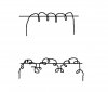
Look at my mspaint picture. Which one of those methods should i use? Would some of them work at all?

How how can i expect the output to be? Guess it depends on how many rotations i make.

I hope you understand my english :wink:
 

Attachments

  • spole.JPG
    spole.JPG
    21.5 KB · Views: 419
There a lot of ways to do this. have u ever seen dynamos? The rotor of which rotates as the wheel of a bicyle rotates. The ouput voltage is proportional to the RPM.

U can also attach a smal magnet to the wheel and use a Hall effect sensor.
U can also use an encoded disc attached to the wheel which moves between the reciever and transmitter of an optocoupler...... there are several ways.............


- Ali Sajjad
 
You might find that a few turns of wire around the PRIMARY of the ignition coil will deliver what you need in terms of information. I would think that a small coil located anywhere on the vehicle would see the ignition. You might take an AM radio and use that. It would seem that in close proximity the electrical spikes from the ignition would overwhelm anything else.
 
What about using a non-inverting opamp circuit? Place a cap in series with the + input to eliminate the DC component, and then amplify the noise. How would this work?

There's a forum with someone that took two wires from his ECU and wired them together, then used that new signal as the input to his tach. Every time his fan kicks on his tach dies. I told him to try that opamp circuit. Don't know what the results would be, but its got to be better (and potentially less destructive) than wiring two unknown wires together.
 
I tried the second method in my picture today. I rounded the secondary wire from the ignition coil. I meassured it with a scope. There is a signal of about 100-500 mV. Can i amplify this with a single transistor, or do i need an power amp?

I have a amp at home that i have never used, LM358.

Can someone help me with the scematics to ampilfy the output to about 5 to 10 V.
 
Alternate tach source - your alternator!

Several circuits use the signal from the alternator to determine engine speed. The regulator is a p-poor filter, and there's plenty of ac signal across the battery to use as an input to an op-amp. Hope that helps....
 
Status
Not open for further replies.

Latest threads

New Articles From Microcontroller Tips

Back
Top