Continue to Site

Welcome to our site!

Electro Tech is an online community (with over 170,000 members) who enjoy talking about and building electronic circuits, projects and gadgets. To participate you need to register. Registration is free. Click here to register now.

  • Welcome to our site! Electro Tech is an online community (with over 170,000 members) who enjoy talking about and building electronic circuits, projects and gadgets. To participate you need to register. Registration is free. Click here to register now.

ID this motor?

Status
Not open for further replies.

dknguyen

Well-Known Member
Most Helpful Member
**broken link removed**

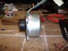
Well, I'm not realy looking for an ID on the motor. I'm actually wondering what type of brushless motor has 7 wires coming out of it. Or is this more of a stepper motor? It's advertised as a brushless motor.

One other thing that might help narrow down what it really is...the RC servo motors are tiny- they have somehow found a way to squeeze all the drive electronics, whatever they are into that space.
 
Most (all?) stepper motors are brushless, I've never seen one used in a servo but that sure looks like one. I bet that thing has a beastly amount of holding torque. I'm guessing it's a 6 wire stepper with a 7th for an internal tach/decoder?
 
You'd think so wouldn't you? But no, the torque on that servo motor is spec'd quite in line with other brushed servos.

So you mean a stepper like the attached schematic? Does it matter whether common green wire is tied to +V or ground? I don't think it does because it just means you commutate in the opposite direction. Connecting common to +V would make it really convenient since you could just use low-level NMOS for everything. THen it would be even simpler than an H-bridge for a brushed motor.
 

Attachments

  • fig05.gif
    fig05.gif
    4.2 KB · Views: 270
Last edited:
I've tied steppers to V+ before for the same reason, there's no reason not to as long as the case isn't 'grounded'. Using meter on continuity should help you figure out which wires are which coils, depends on what that 7th wire actually is though. You'll find a single resistance for each coil, if you get double that resistance you know you're measuring continuity across two coils.


I just took a closer look at that picture, it looks like it has 8 wires? 8 wire steppers are just two wires per coil and can be simplified by tieing all the commons together and using it like a 5 wire stepper, would seem silly to put a tach on a servo drive cause they're usually direct read from a pot attached to the output shaft.
 
Last edited:
It's geared and the output shaft after reduction is tied to an output shaft. THe motor would rotate many many times for one rotation of the pot (and it has gear stops so it wouldn't rotate more than about 180 degrees anyways). I'm not sure how you would know when to commutate the motor without an output signal.

I was just curious...these servos are too expensive right now for me to open up and gut.
 
Last edited:
I have a big dc brushless servos it has 9 wires I was hoping you
I was just curious...these servos are too expensive right now for me to open up and gut.
:D so maybe I wouldn't have to :D i been trying to see how it worked I have the controller board for it.
 

Attachments

  • GEDC0364.JPG
    GEDC0364.JPG
    40.2 KB · Views: 280
Actually my interest was just placing serial controlled electronics in place of those in the servo. Still hunting for a servo with good mechanics but isn't overpriced for gutting.
 
Why bother gutting them? A small micro controller circuit can be used to take in serial commands and output analog servo signals extremely easily without altering the servo's electronics.
 
Why bother gutting them? A small micro controller circuit can be used to take in serial commands and output analog servo signals extremely easily without altering the servo's electronics.

Because I want CAN servo with external servo position feedback and cycle-by-cycle current limiting. A controller that accepts serial commands and outputs PWM for the servos is a moot point because that'd just be the autopilot.
 
Last edited:
CAN bus = Controlled Area Network - some RS-485-like asynchronous differential multi-master protocal that has built-in addressing, error checking, and non-destructive arbitraiton (message collisions do not destroy the information on the line currently being sent)

Cycle-by-cycle Limiting - every PWM pulse runs like it normally would but if a fault is detected the pulse is forced inactive and remains that way for the remainder of the pulse period. This is reset at the beginning of the next pulse. It basically means that with this current limiting, the motor will try to do as much as it can with the power available imposed by the current limit. Battery voltage cycle-by-cycle means the same thing...it will do as much as it can without the battery voltage drooping below the threshold.

It's kind of like what you do. If you lift something that is too heavy you don't just stop lifting it and let it drop nor do you continue to try to lift until you destroy your arms. You try to do as much as you can without damaging yourself (ie. lowering it towards the ground slower than what it would fall at).
 
Last edited:
CAN is a serial bus protocol, and dkn said basicaly they want control over the PID loop of the servo for some reason.
For that kind of use pretty much any servo will do. What exactly are you going to end up driving with the modified servo?
 
It's for the swashplate and tail pitch slider of a helicopter which is why I'm somewhat stuck with the physical model of an RC servo.
 
Last edited:
CAN bus = Controlled Area Network - some RS-485-like asynchronous differential multi-master protocal that has built-in addressing, error checking, and non-destructive arbitraiton (message collisions do not destroy the information on the line currently being sent)

Ah, I know what CAN is but "can servo" was not ringing a bell :D so .. you want servo with a CAN interface .. Don't you find easier to add a small pic&can interface adapter on 1x2cm board glued to the "standard servo" then gutting the servo, changing the driver with your own elco that you then need to fit inside???

Cycle-by-cycle Limiting - every PWM pulse runs like it normally would but if a fault is detected the pulse is forced inactive and remains that way for the remainder of the pulse period. This is reset at the beginning of the next pulse. It basically means that with this current limiting, the motor will try to do as much as it can with the power available imposed by the current limit. Battery voltage cycle-by-cycle means the same thing...it will do as much as it can without the battery voltage drooping below the threshold.

interesting, thx for the explanation

It's for the swashplate and tail pitch slider of a helicopter which is why I'm somewhat stuck with the physical model of an RC servo.
hm .. how big that copter is if you have to implement CAN to "talk between the parts" ?
 
Ah, I know what CAN is but "can servo" was not ringing a bell :D so .. you want servo with a CAN interface .. Don't you find easier to add a small pic&can interface adapter on 1x2cm board glued to the "standard servo" then gutting the servo, changing the driver with your own elco that you then need to fit inside???
THat won't work for the external feedback part. I am strapped for space though and am trying to find ways to fit more PCB inside the servo in case I can't fit everything onto the PCB (like stacked PCBs inside the servo or makine some things external. But if you've looked at how servos are mounted in the helicopters, you can't stick anything on the sides of the case because it interferres with them sliding into the mounting slot. sticking things on the back also makes the servo too tall and so it hits the servo on the opposite side during mounting.

hm .. how big that copter is if you have to implement CAN to "talk between the parts" ?

1.2m diameter rotor blades with about ~3kg weight. I don't want to use something like I2C because it might have trouble with the noise going around. In this case, CAN also has the weakness of one cable used to transmite everything (daisy-chain vs star network) so if the cable snags somehow things could go bad. I might loop it all the way around again to a second CAN port on the controller so if something happens to the cable in the middle it can still communicate both ways.
 
Last edited:
Status
Not open for further replies.

Latest threads

New Articles From Microcontroller Tips

Back
Top