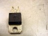
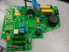
I have two ABB motor drive boards that were burned, and one that is new and working. It is used to open and close a 3 pole 400 amp breaker. I need to replace a device on the two bad boards that are shorted, and I cannot ID the part on the good one. It has a mounting tab like a 12 v, or 5v regulator and 3 leads out the bottom; looks exactly like a TO-220 device. An ohmmeter on the two outer leads reads 40 ohm in both directions using a Simpson 260. Same test with a Fluke DVM shows 60 ohms each way. The middle lead shows an infinite resistance to the other two. There is no connection to the tab from any of the 3 leads. Using 250 VAC to the left-most lead, the right-most lead measures 250 VAC also. There is zero volts on the middle lead. Activating the motor drive, a momentary 250 VAC to one pole of the motor, the motor turns through several cycles, then stops when a series microswitch is activated in one lead of the motor. The motor is AC or DC with brushes, I think it is known as a Universal Motor. Once the motor stops turning, then I have 12 VAC on the center lead of this device. The motor cycle has completely opened the breaker at this point. Then I momentarily switch 250 VAC on another lead to activate a solenoid to latch the circuit breaker to a fully closed position. ABB is of zero help with this--no schematic, no ID, will sell a new one to me for $ 2000.00--that's their help.
The bad devices are shorted to zero ohm on all 3 leads, but still no connection to the mounting tab. I've looked at all the Triacs, Diacs, IG, Quadrac, Alternistor, etc, and cannot decide which, if any, are likely to be the ID. No, there are no markings of any kind on the component in question.
There is a Toshiba TLP3022 Optical LED Triac in series with the lead on the right-most side. This keeps the motor running after the momentary contact gets it started. Then the motor stops when a cog hits the microswitch. Opening the middle lead of the device, activating the momentary 250 VAC will start the motor, but a series 215 ohm resistor burns up in the output of the TLP3022 in series with the motor drive. I guess the motor drive might be sharing the motor load through the center lead and the lead through the Led Triac?
Any suggestions from anyone other than spending $4000.00 would be appreciated.