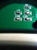
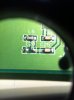
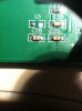
L5 was most likely originally intended to be a ferrite chip, its purpose to suppress noise coming in on the trace. They are effectively inductors, hence the "L" designator prefix. Sometimes after design and testing they are deemed unnecessary and are replaced with 0 ohm (jumper) resistors during assembly. I am willing to bet that is exactly what happened in this particular case. You can probably replace it with another 0 ohm resistor and not have a problem.