Continue to Site

Welcome to our site!

Electro Tech is an online community (with over 170,000 members) who enjoy talking about and building electronic circuits, projects and gadgets. To participate you need to register. Registration is free. Click here to register now.

  • Welcome to our site! Electro Tech is an online community (with over 170,000 members) who enjoy talking about and building electronic circuits, projects and gadgets. To participate you need to register. Registration is free. Click here to register now.

ICM7555 IC duty cycle limit at high frequency?

Status
Not open for further replies.

Flyback

Well-Known Member
Hi,
ICM7555 has a max frequency of 500kHz. (T=2us) However, pg 8 Fig 9 says there is a ~250ns propagation delay when vdd=5v.
That must mean that the duty cyle when at 500kHz must be limited to 0.75 maximum?

ICM7555
https://www.nxp.com/docs/en/data-sheet/ICM7555.pdf

Do you know what the max duty cycle can be of the output at 120kHz?

Just noticed the graph, Fig 12, on page 10 of the ICM7555 datasheet is incorrect.....it gives RA=RB=1k and C=7nF giving 200kHz....whereas the equation (1) on page 12 gives that as 65.7kHz.

___***___
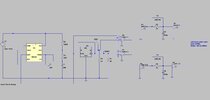
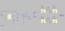
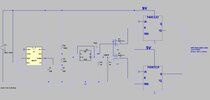
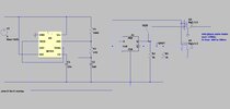
Basically, we need the following attached 555 based sync’ing cct to be able to deliver pulses of <500ns width at 240kHz. So the 555 output must be 240kHz, with a duty cycle of no less than 0.91. Do you think this is possible with a ICM7555?

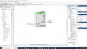
LTspice and jpeg attached of sync’ing cct (it syncs a UCC28070A)
 

Attachments

  • 555 cct.jpg
    555 cct.jpg
    117.5 KB · Views: 199
  • 555.asc
    3.4 KB · Views: 172
Last edited:
Thanks very much, those are good chips.....i see the 74HC4046 is a 50% duty cycle oscillator, and the 74HC123 i would need a pulse train to keep triggering it...and the pulses would need to be <400ns length in my case....but if i had that i wouldn't then need the 74HC123. Its a shame that the 74HC123 can't be prevented from retriggering.......having said that, the 74HC123 gives a very accurate pulse width so i may use some differentiator pulses to then keep triggering the 74HC123....it looks like the 74HC123 needs a pulse input of >25ns to work......so i will give it a train of ~200ns input pulses, and set the output pulse width to 400ns with R and C selection.

The attached is the way I believe I will go now…….i may later enhance it by putting a 74HC123 at the output, to make the pulse widths more exact....i may just use SOT23-5 gate drive ICs instead of the buffers...the buffers only come in SOIC16.

LTspice and jpg schem attached.
 

Attachments

  • 400ns pulse trains.asc
    5.4 KB · Views: 177
  • 400ns pulse trains.jpg
    400ns pulse trains.jpg
    114.3 KB · Views: 178
Last edited:
The attached is the finished version of 400ns pulse trains...any improvements greatly appreciated...
LTspice and jpeg
 

Attachments

  • 555_fet drivers.asc
    5.9 KB · Views: 183
  • 400ns pulse trains with fet drivers.jpg
    400ns pulse trains with fet drivers.jpg
    131.5 KB · Views: 180
For future reference this can be done simply using a SOC low end part, PSOC 4M.
Single chip, you need just one external C for bypass power.

Simply drag and drop the PWM, PINs, and Clock resources out of the chip resource
catalog, route them, wire to each other, and double click to config period and desired
pulse width. Can operate as a one shot from an edge signal or just continuous.

One instruction has to be typed into C file, a start instruction for the PWM, done.

Note many other chip resources still available for other stuff, see below. Also see
right hand window for design resources used/left.

Timing accuracy over T and V is +/- 2%. I set it for 400 nS thinking you wanted it no more than
500, but then saw later your note 400 - 600, so simple to change that in settings.


1656544375928.png


1656545271042.png


Other stuff on chip....multiple copies of many....


1656545372350.png


Regards,. Dana.
 

Attachments

  • 1656543597661.png
    1656543597661.png
    264 KB · Views: 186
Last edited:
Just connect whichever input you are not using to the appropriate output and retrigger is blocked.
Thanks, ive actually seen that with 74HC123, it is edge triggered, so the input pulse being longer than the monostable interval (400ns) shouldnt matter?....ie, If A goes high for 1us, the Q will go high for 400ns, then go back low again, even though A is still high for another 600ns.
The attached is the latest, any improvements greatly appreciated.

CD74HC123 Monostable IC datasheet:-

.....Also, if one of the monostables on a CD74HC123 chip isnt used, would you agree, the CX , RxCx, A, !B and !R pins should all be grounded?
 

Attachments

  • 555_74HC123.asc
    4.4 KB · Views: 184
  • 400ns pulse trains with monostables.jpg
    400ns pulse trains with monostables.jpg
    125.6 KB · Views: 203
Last edited:
A 555 is totally unsuitable for stable high speed applications such as that.
Thanks, i wasnt sure if sync'ing the UCC28070A really needs to be that "stable", or "high speed"?.....i am operating each booster of the UCC28070A at 60kHz......so i need a 120kHz sync pulse train....the pulses should be no shorter than 200ns, and preferably 400-600ns.
Surely a 555, with a CD74HC123 to trim the pulses down to 400ns will be OK for this application?
 
If you dont care about T and V and your pulses, designed for 500 ns, are +/-50% off
( 250 ns to 750 ns) you are good to go.

The 74HC123 is so poorly characterized in data sheet one might as well use a pulse
derived from a random person blowing on a whistle. Just the prop delay variation,
only partially shown in datasheet, might have the circuit missing pulses in the input
trigger train.

And thats just the mono, let alone passive problems, and get ready the 555 precision of
a 2 digit calculator. is not going to help either.


Regards, Dana.
 
Last edited:
Status
Not open for further replies.

Latest threads

New Articles From Microcontroller Tips

Back
Top