Continue to Site

Welcome to our site!

Electro Tech is an online community (with over 170,000 members) who enjoy talking about and building electronic circuits, projects and gadgets. To participate you need to register. Registration is free. Click here to register now.

  • Welcome to our site! Electro Tech is an online community (with over 170,000 members) who enjoy talking about and building electronic circuits, projects and gadgets. To participate you need to register. Registration is free. Click here to register now.

IC 7404 (Not Gate) Doubt !

Status
Not open for further replies.

Electroenthusiast

Active Member
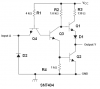
I wanted to realize the Not Gate using the Breadboard.
So i made the required connections.
But to my surprise, i saw that the light used to glow even if there was No Gate Input (I1), actually the output did not change if i removed the Input Connection(I-1) of Not Gate.
And i wanted to capture the effect using the Camera, as i brought the camera near it, LED used to ON/OFF based on the distance b/w camera and Circuit.
(Input IS not Vcc, its input of the gate)

May i know Why all these are Happening?

Here are the Images...(Click on it to Enlarge)

P1040172_12..jpg
 
Last edited:
Logic levels are 0 and 1.

When you leave a input without any connection then you are making it float/leave it at high impedance and you are going to get weird results, specially if you are using a CMOS family, for example, 74HC04:

When you ground the input, you are going to discharge the Gate-Source capacitance, after that if you simply leave it unconnected, you are never (ideal model) going to let the Gate-Source capacitance to be charged again, leaving the output High.

The same thing happens when you connect the input to V+. You charge the Gate-Source capacitance, and if you disconnect the input from the circuit, the Gate-Source capacitance will remain (ideal model) charged forever, therefore the output will remain Low.
 
Per Hayato it looks like you have a 7404 Hex Inverter. All unused inputs need to go somewhere. So if you are using pins 1 in and 2 out then pins 3, 5, 9, 11 and 13 need to be tied to either high or low for the chip to work. Just remember all unused inputs must be tied to VDD (+) or VSS (-) or erratic chip behaviour will occur and excessive current consumption will occur.

Ron
 
In short you should connect the to 0V via a pull down resistor, any value between 1k and 1M will do but I generally go with 100k.

Ideally all unused gate inputs should be connected to either 0V or +V but in this case nothing bad will happen if you don't.
 
Per Hayato it looks like you have a 7404 Hex Inverter. All unused inputs need to go somewhere. So if you are using pins 1 in and 2 out then pins 3, 5, 9, 11 and 13 need to be tied to either high or low for the chip to work. Just remember all unused inputs must be tied to VDD (+) or VSS (-) or erratic chip behaviour will occur and excessive current consumption will occur.

Ron

Why?
How does it effect the working of the 1st Gate?
 
I forgot, it's TTL so ignore my previous post, I'm used to CMOS.

With TLL the input defaults to high, look at the internal schematic per gate.

You should connect the switch to 0V or use a 1k pull down resistor.

Anyway, I'd recommend using LS or CMOS, no one uses TTL these days.
 
Why?
How does it effect the working of the 1st Gate?

Noise internal to the chip. Figure it this way, you have an inverting hex inverter. Its sole purpose in life is changing an input to a complimentary output. The 7404 and the 74LS04 are hex inverters and the 74LS04 is a lower power LS (Low power SCHOTTKY) design.

When you have unused inputs just floating around they act like tiny antennas and the chip sort of freaks out and can go into weird oscillations. This results in considerable noise within the chip. The adjacent inverters are open to this noise.

Also I said to tie unused inputs to high or low and I should have specified through a pull up or pull down resistor as Hero mentions. The thinking being if we just tie an input to the 5 volt bus and that input shorts to ground then bad things will happen.

covers things in pretty good detail and a Google of "Unused inputs on a TTL chip" will bring up countless hits.

Ron
 
I forgot, it's TTL so ignore my previous post, I'm used to CMOS.

With TLL the input defaults to high, look at the internal schematic per gate.

You should connect the switch to 0V or use a 1k pull down resistor.

Anyway, I'd recommend using LS or CMOS, no one uses TTL these days.
I think it is CMOS. The OP said:
And i wanted to capture the effect using the Camera, as i brought the camera near it, LED used to ON/OFF based on the distance b/w camera and Circuit.
TTL would not do this. CMOS would.
 
I think it is CMOS. The OP said: TTL would not do this. CMOS would.

TTL would do it I think and the OP specifically said "IC 7404 (Not Gate) Doubt" ! and that seems to point to TTL. I guess we could wait for the OP to return with a more specific part number?

Ron
 
Roff is right, TTL won't do that unless the leads are insanely long.

TTL inputs default to high; this can be figured out by looking at the internal schematic on the data sheet, if you don't understand it, try simulating it.
 
This is part of a read on the subject:

What should I do with the UNUSED INPUTS?
TTL devices normally default to a logic ONE if the input is allowed to FLOAT.
However, depending on many factors, these inputs can act as an antenna, and pick up NOISE which can cause mischief to the circuit. The worst case is, the device will act as an uncontrolled intermittent OSCILLATOR. --This is BAD!

Therefore:
ALL unused inputs of TTL logic devices IDEALLY should be returned to either a logic ONE or logic ZERO. Certain devices--74XX and earlier 74LS--the logic ONE (Vcc) should be a ~ 1k resistor to Vcc; or alternatively, connected directly to ground (ZERO). Most/All other logic devices, the resistor is UNNECESSARY.

In the case of CMOS devices, there is NO input DEFAULT; CMOS input impedance is on the order of thousands of MEGOHMS and will cause EXTREME FAILURES if allowed to FLOAT.

To make this point: if you put your finger or a scope probe on or NEAR an un-terminated CMOS input, it can cause a logic CHANGE!! If allowed to float, some CMOS devices can oscillate so fast, that it exceeds the device power rating and will literally destroy itself.

Unused Outputs: tri-state[1], and open collector devices, etc., DO NOT require any attention.
NOTE: In the case of the tri-state control pin, it should be treated as an INPUT.

Notes [1] Tri-state: Zero, One, Open.

WARNING:
NEVER EVER USE the original generic 7400 DEVICE.
INSTEAD: Use anything else, e.g., 74LS, 74ALS, etc.
The older devices require five to ten times the drive power and force very LARGE amounts of NOISE on to the Vcc rail! --This is NOT GOOD!

The above taken from here.

Then there is this link which goes into great detail on the use of and calculating pull up or pull down resistance values. Me, I generally just tie unused inputs to ground and for a pull up use 1K. Then too as was pointed out you don't build anything new with a 74XX TTL chip.

Ron
 
Just because it says so on some website, it doesn't mean it's right.

Have you looked at the internal schematic or simulated it yet?
 
Just because it says so on some website, it doesn't mean it's right.

Have you looked at the internal schematic or simulated it yet?

Thanks Hero I was aware that just because it is on the web does not make it gospel. I am also aware that a simulation doesn't always tell the truth. I gave two links and they conflict. Matter of fact if you Google "TTL unused inputs" you get a host of hits with various answers on what to do.

Now, the OP has yet to return and we have no clue other than 7404 as to what he actually has for a chip. I have had old 74XX gates with open inputs simply go into oscillation and screw the other outputs. Now I figure rather than speculate as to what the OP has it would be wiser to wait and find out.

Ron
 
For the OP description, he is using the HC/HCT family.
That makes more sense.

Thanks Hero I was aware that just because it is on the web does not make it gospel. I am also aware that a simulation doesn't always tell the truth. I gave two links and they conflict. Matter of fact if you Google "TTL unused inputs" you get a host of hits with various answers on what to do.

Now, the OP has yet to return and we have no clue other than 7404 as to what he actually has for a chip. I have had old 74XX gates with open inputs simply go into oscillation and screw the other outputs. Now I figure rather than speculate as to what the OP has it would be wiser to wait and find out.

Ron

Just for future reference, attached is the internal schematic for the SN7404.

Can you tell me what will happen if the input is left disconnected?

If not I'll help but someone else here will probably beat me to it.;D
 

Attachments

  • SN7404..PNG
    SN7404..PNG
    4.8 KB · Views: 2,404
Can you tell me what will happen if the input is left disconnected?

TTL inputs have to have a lot of current (1.6 mA in real 7400 series) pulled from the input to force the input low.

If the input is open, it pull high and the input transistor (Q4) turns off. Then what happens is that current flows through the PN Base - Collector junction of Q4. That turns on Q3, so Q1 turns off and Q2 turns on, with the output low.
 
What he said. :)

Letting the input float will generally make it go high (logic 1) but since it is floating it is open to noise so it may not remain where it wants to go. Therefore we shove a pullup resistor on it and tie it to VCC. The bottom line is when working with circuits like this all unused inputs need to go somewhere.

Looking at original post and the images it looks like his problem is caused by floating unused inputs.

Ron
I think most of us old timers know that it is poor (unacceptable) practice to leave TTL inputs floating. Nevertheless, you cannot play them like a theremin using the proximity of your hand (or other large body), which is what the op described. Not a theremin literally, of course, but a "light modulator".
If he truly has a 7404, then he must have some serious AC riding on his body. I'm not convinced even that would cause this effect.

EDIT: I just remembered that the described (and photographed) the LED as staying on after he removed the ground connection to the input. This can only happen if the input is storing charge. TTL can't do that.
 
Last edited:
Yes, imagine the capacitive impedance between him and the open circuit TTL input. He'd have to be charge to a pretty high voltage or have a pretty high frequency field connected to him to induce 1.6mA of current in the input.

It's far more likely he's using the CMOS version, as mentioned above.
 
Ron,

I agree with you, we must not leave any floating input in logic circuits.

But TTL logic (LS/S/plain) is has some immunity to floating inputs, observe that the input section reminds us a common-base amplifier, which means that it has a low impedance input -> "High current" to drive it. (from 20uA to 400 uA against the 1uA from a HC family).

The OP describes he has some sort of "histeresys" on his circuit:
-> He pulls the input down and then makes it Hi-Z, but the output behave like if the input was still pulled down.
-> He pulls the input up and then makes it Hi-Z, but the output behave like if the input was still pulled up.

The circuit is not behaving randomly, it just has memory, so IMHO it is not a noise problem.
 
Status
Not open for further replies.

Latest threads

New Articles From Microcontroller Tips

Back
Top