Continue to Site

Welcome to our site!

Electro Tech is an online community (with over 170,000 members) who enjoy talking about and building electronic circuits, projects and gadgets. To participate you need to register. Registration is free. Click here to register now.

  • Welcome to our site! Electro Tech is an online community (with over 170,000 members) who enjoy talking about and building electronic circuits, projects and gadgets. To participate you need to register. Registration is free. Click here to register now.

I want to build an alternating BLINKY (multivibrator circuit) using TRANSISTORS , can you help me?

Status
Not open for further replies.

Tom1951

New Member
I am new to this forum and this is my first post or question, I would not bother you but I am striking out elsewhere on the web. I did search this site too without success, however the circuit I want is a very common and old circuit I think there’s one here I just can’t find it.

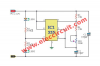
After some informative and appriciated replies I have decided to use transistors only... the 555's are out. So I still need 1 good schematic for this. The ones on the web are energy wasters. These binkys will be left on until the battery dies. My father in law made blinkys for his 5 children in the 60's and all 5 tell me they were never turned off (no switch) and lasted as long as they can remember... I know, you're thinking the same thing I am, "that's impossible". I think he was secretly changing the batteries because he had to use incadescent bulbs and they eat juice! So if you folks don't mind can we have another go at it.

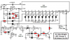
I want to build the young ones a “BLINKY” box. I am having difficulty finding a “Good” circuit schematic on line. I believe the correct name is a multivibrator circuit. I actually would like 1 circuit diagrams using transistors. I want to use 2 LEDS and have the LEDS flash back and forth. I also want to vary the alternating flash rate with pots. The blinky box will be powered by 9 VDC battery and mounted in a small box the children can place next to their beds.

The problem with many of the circuits on line is they are battery eaters. They work alright for a week or 2. Most of them Place resisters across battery terminals (even going thru transistors) this will allow the battery to last only a week or 2. Transistorized blinkys can last an incredibly long time. I built one with a solder type pc board and 555 IC timer, next time I want to use solderless breadboards to verify it works the way I want it to. This is because the flash rate was erratic at best, one side was slow and bright and the other was fast and dim. I want the light to blink symmetrically.

I would greatly appreciate someone providing me a circuit diagram or a hotlink to one as I described, in advance, Thank You.

Tom
 
Last edited:
I have some red blinkers that use two alkaline AA cells that last for 3 months. I do not use a current-hungry 555 instead I use a Cmos gate IC as the oscillator and a Cmos 74HC4017 to drive 10 LEDs, one at a time. Another design uses four AA alkaline cells that last for 3 months and has higher voltage blue and green LEDs.

The key to low current is to blink each LED for only 30ms then a pause before the next LED blinks, and after the LEDs go around and around in a circle a few times there is a couple of seconds pause with no current used before it starts again.
Here is my circuit:
 

Attachments

  • 3V_Chaser_2.jpg
    3V_Chaser_2.jpg
    49.7 KB · Views: 200
  • New 3V Ultra-Bright Chaser.PNG
    New 3V Ultra-Bright Chaser.PNG
    149.1 KB · Views: 219
  • 3V Ultra-Bright Chaser-2 parts list.PNG
    3V Ultra-Bright Chaser-2 parts list.PNG
    25.2 KB · Views: 194
As AG said, off-time = battery life. With a simple 555 circuit and two LEDs, one or the other is on all of the time. So the battery life is less than just having one LED on constantly because the 555 circuit uses some current that doesn't go through either LED. There are several ways around this. One is to look into joule thief circuits. These are extremely efficient LED blinkers designed to use the last ounce of charge in an otherwise useless battery. Another is to have the timing capacitor charge dump into the LED so you get double-duty out of those electrons.

ak
 
In my LED projects where the battery lasts for 3 months, the LEDs blink and are OFF most of the time. Simply using a multivibrator so that there is always one LED lighted and the continuous current in the ordinary 555 will kill the battery in a short time.
 
I have some red blinkers that use two alkaline AA cells that last for 3 months. I do not use a current-hungry 555 instead I use a Cmos gate IC as the oscillator and a Cmos 74HC4017 to drive 10 LEDs, one at a time. Another design uses four AA alkaline cells that last for 3 months and has higher voltage blue and green LEDs.

The key to low current is to blink each LED for only 30ms then a pause before the next LED blinks, and after the LEDs go around and around in a circle a few times there is a couple of seconds pause with no current used before it starts again.
Here is my circuit:

Nice use for a discarded CD.
 
There is an obsolete IC called LM3909 attached. You might not be able to get them now cheaply, but you can construct it using discrete components.

lm3909 cct.png
lm3909 internal.png
lm3909 3TR.png


1st one is the wiring of the chip.
2nd one is the internal, all the values are there.
3rd one is the 3 transistors version.

I used them as dummy alarm near my doors and windows, to scare off the thieves. 2 AA battery for each circuit would last for months.

Allen
 
Last edited:
the 2.4V flashlight bulb heats up / reaches it's full intensity basically as fast as it and fades to non-glowing
that time is about 240ms roughly ¼ of a second (to light up and another ¼ of a second to fade off)
by that time it drains in rough average
850mA·2.4V·240ms=133µW·h *** (2Ω cold to 4Ω hot) ***
850mA·240ms=57µA·h
the mA·h capacity of AA is some 600 to 800 in over avg. drain (up to 1800 2600) at 1.46V down to 900mV
so it - the blinker - could do for alkaline's ⁴√(600·800·1800·2600) = apx. 1200mA·h
1200/.057 = apx. 21000 full brightness blinks
at 2 flashes per second it'll do 10500s or 2.92 hours , 1f:6h , flash every other second 12h , e.c.

there're are 1.5V bulbs that draw ... 60mA
making the table look like for avg 85mA *** (1.5V/.06A=25Ω hot down to apx. 12.5Ω cold) ***
2Hz : 30h , @ 1s : 60h , @ 2s rate : 5 days , e.c.
 
Many Thx to/for everyone’s comments. My father in-law was a practical joker. I believe he was changing the batteries w/o his children knowing about him doing so. I believe the 50’s & 60’s only had lead acid batteries readily abundant and available.

I had not really thought out how long a battery would last because, “they all told me…”. So I am going to build my blinkys using 9VDC or 12 VDC Wall Wort (power supply). I want the children to see their blinkys “running forever” too :). Ah, the innocence of children, wait a minute, I’m 65 YO – I should have known better.

Thanks Again Folks!

PS. When I finally acquire ALL the components (eBay can be slow when coming from China) I’ll post the final outcome. May be a couple (or more) months from now. Tally Ho.
 
there is said in the old radio magazine that alternating the flashlight @ apx. 20Hz would extend the battery life by multiples ???
also there's this
which i think can be set up as a pulse packet generator to power capacitive voltage multiplier for . . . whatever ....
nothing to do ...
???
 
In 1992 I built a Christmas tree that had 8 strings of 4 LED's in series, two strings were in each collector. The circuit was very close to the attached file.transistor flasher.png
I used 56K resistors instead of the 100K resistors. There were four LED's is series and a 68Ω resistor was used instead of the 470Ω. The LED's would flash normal for over 1 week continous with a 9V alkaline battery.
He Tom1951, if you like, tell me what circuit you plan to use. I will be glad to send you the parts via USPS to you in Pennsylvania at no cost. Just send me a PM(personal message) and I'll get the parts off to your. Ned
 
Thx to Reloadron, I found a "Blinky" schematic I like. Ned I PM'd you, hopefully you received it. This is the schematic I plan to use. I am using a 9 VDC wall wort so battery consumption won't be a problem. This dwg. allows the flash rate to be varried from slow to steady state. The LEDs flash symetrically too. I'm just not sure if the 100uf cap is needed, not sure what it does. Tom

upload_2017-5-17_16-36-47.png
 

Attachments

  • upload_2017-5-17_15-44-58.png
    upload_2017-5-17_15-44-58.png
    283.7 KB · Views: 156
Thx to Reloadron, I found a "Blinky" schematic I like. Ned I PM'd you, hopefully you received it. This is the schematic I plan to use. I am using a 9 VDC wall wort so battery consumption won't be a problem. This dwg. allows the flash rate to be varried from slow to steady state. The LEDs flash symetrically too. I'm just not sure if the 100uf cap is needed, not sure what it does. Tom

View attachment 106037
Tom I can't find the PM you sent,Ned
 
The 100uF is a supply bypass capacitor but some people say it decouples the power supply. It is important for most circuits even if the power supply has one because the wires from the power supply have series inductance that causes the voltage at the circuit to jump up and down with loading. The old ordinary 555 causes a 400mA power supply current spike each time its output switches and the capacitor supplies this current. The datasheet of an LM555 talks about this capacitor.
 
Status
Not open for further replies.

Latest threads

New Articles From Microcontroller Tips

Back
Top