Continue to Site

Welcome to our site!

Electro Tech is an online community (with over 170,000 members) who enjoy talking about and building electronic circuits, projects and gadgets. To participate you need to register. Registration is free. Click here to register now.

  • Welcome to our site! Electro Tech is an online community (with over 170,000 members) who enjoy talking about and building electronic circuits, projects and gadgets. To participate you need to register. Registration is free. Click here to register now.

I need Ideas/Suggestions

Status
Not open for further replies.

drkidd22

Member
Hello,

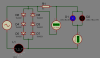
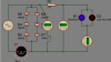
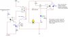
I havethe circuit diagram below. I did it with multisim. But before I go on ordering parts I will like ideas/comments/suggestions about it. If there is anything I should change or should have done differently. I want this circuit to be safe and of a commercial grade, even dough I'm only going to use it in a few rooms. The concern I have is with the power consumption of the resistor to drive the ac optocoupler. at 120V power is low at about 1.2W, but if I was to use 240V then it goes up to 4.8W. I was thinking of using resistors in parallel to account for this, but if anyone has a better idea, let me know.

Circuit is simple. A three way switch to control the light independent of the Pic. and a relay which is controlled by the PIC. The AC opto is used to tell the Pic if the light is on/off
 

Attachments

  • accontrol.JPG
    accontrol.JPG
    42.3 KB · Views: 458
Any chance that you can put this in series with the lamp instead of parallel to it? No big dropping resistor, and it will work with any AC voltage above ~3VAC. It also indicates if the lamp is burned out. PIC tries both switch options, and if no output, the lamp is open. C1 isn't needed if the PIC just needs to see the 50/60 HZ pulsing DC.

Ken
 

Attachments

  • Line Detector.gif
    Line Detector.gif
    15.7 KB · Views: 290
Last edited:
So, what you are really doing is just using the diodes to dissipate power instead of resistors. The opto you are using is not for AC, not a big deal, but I'll rather have a logic out.
 
Yes, sort of. D1 acts as a -0.6v shunt regulator and dissipates 0.6v x load current for one half cycle. D2/D3/D4 act as a +1.8V shunt regulator and dissipates 1.8V x load current for the other half cycle. Total dissipation is ((0.6xI)+1.8xI)/2). Your resistor's dissipation is proportional to line voltage. My diodes' dissipation is proportional to load current. The higher the load current, the less advantage mine has. ;)

What optocoupler are you using that has an AC input and a logic output?

Ken
 
For the AC opto I'm using the PS2505 from NEC, which requires 10mA (this is where I have the power dissipation concern), and for the pic to drive the relay is PS2501A with a 5V relay. I was going to use a 3V relay, but I think 5V should be ok.

What diodes should those be? I can build both circuits and see what happens.

With that circuit you posted, aren't you putting in > 1A to that opto? Looks like it will blow up, or I might not be understanding something. Explain please.

thanks,
Jose
 
Last edited:
For the AC opto I'm using the PS2505 from NEC, which requires 10mA (this is where I have the power dissipation concern), and for the pic to drive the relay is PS2501A with a 5V relay. I was going to use a 3V relay, but I think 5V should be ok.
https://www.cel.com/pdf/datasheets/ps2505.pdf see Electrical Characteristics
The 10 MA If for the LED is what is needed to drive a Ic of 50mA. Since the your output, LED/resistor, only draw 20mA, you might be able to get by with a lot less current on the PS2605's LED. I would try it on a bench supply just to see.

With the resistor, LED, Relay, and transistor in series, you will never get the relay to turn switch. In fact using a 5V relay on a 3.3V supply would be marginal at best. Also the arrangement of R2 and LED1 will not give you logic level signals into your PIC.

What diodes should those be? I can build both circuits and see what happens.
The diodes can be any silicon power diode with a voltage rating >25VDC and a current rating greater than the current required by the lamp. What's the wattage of the lamps you will be switching?

With that circuit you posted, aren't you putting in > 1A to that opto? Looks like it will blow up, or I might not be understanding something. Explain please.
No. As I said the diodes act as shunt regulators. The resistor and LED are across 3 diodes in series on the positive half of the power line cycle. Each diode drops 0.6v, so three diodes drop 1.8v. That's the peak voltage applied to the 100Ω resistor and LED. 1.8v-1.6v(Vf of the LED) divided by 100Ω equals 2mA. On the negative half cycle they are across one forward biased diode, so see a reverse voltage of -0.6V.


Is there a reason for running your PIC on a 3.3V supply instead of 5V, as I assume you will be powering it off the line through a wall wart?

Ken
 
Another concern is that the PS2505's transistor has an Absolute Maximum Ic if only 30mA: **broken link removed** It will have to handle both the LED2's and relay's current.

Ken
 
The lamps are from sylvania. Flourescent 13W 120V 0.230A. But there might also exist the possibility of running some regular 40-60W 120V filament bulbs.

The PS2605 is obsolete.

I have 240V on the schematic I posted because I was simulating and just wanted to see what the circuit was going to do. I know it's better if done on a bench and I will do so.

The 3.3v was because I wan't to use as less power as possible. Where I plan on using this system we loose power very often and we run on a DC-AC automatic inverter with about 8 high capacity Trojan batteries. Just like on a boat. This gives a couple of days using TV, lights, no fridge, and sometimes the computer is used for a few hours. I know it might make a really big effect, but the less the better.
 
Another concern is that the PS2505's transistor has an Absolute Maximum Ic if only 30mA: **broken link removed** It will have to handle both the LED2's and relay's current.

Ken

That one is for the PS2501A-1 which is 30mA Ic and is single LED. As I Mentioned above, I want to use PS2505A-1 50mA Ic and AC (dual LED).
 
The PS2605 is obsolete.
A typo on my part..I meant 2505.
The 3.3v was because I was't to use as less power as possible.
For the least amount of power during a grid power outage, just unplug the supply for the PIC/light-switch, the manual switch will still work...unless the PIC is doing something else. If it were portable or going to Mars it might be worth the small savings in power. ;)

And, you don' need the optocoupler on the output of the PIC, the relay isolates it. :)

I attached two schematics that might work.

DX is an anti-flyback diode to protect the transistor from the relay's reverse voltage spike when it de-energizes. Best practice is to include it.

In the both schematics the PIC output opto-coupler is replaced by a transistor. Ry is added as a pull-up on the PIC's input. It may not be necessary.
In the first schematic R3's value is still unknown, based on the PS2501's gain. And, by moving the LED to the collector you take full advantage of the coupler's transfer current gain.
The second schematic uses my diode configuration. Again, the diodes's current ratings depend on the IL wattage. It looks the 1N4001s will work.

Ken
 

Attachments

  • PICLightSwitch01.gif
    PICLightSwitch01.gif
    16.1 KB · Views: 192
  • PICLightSwitch02.gif
    PICLightSwitch02.gif
    18 KB · Views: 193
Last edited:
Mars? I don't I'm going there yet, maybe my next life...:)

Yes, the Q1 was going to be my next question and you have answered that.

From both circuit I think the second one will be a better choise for me.

I have not been playing with electronics for a while so I need to look more at the circuit with the diodes (DY) and R3 so that I can understand it a little better.

For you to end up with the 27Ohm you are accounting for the resistance that exists on K1 contacts and whatever the lamp resistance is right? How exactly is this value being calculated?

I have ordered the parts already and will be bulding the circuit once I get them in and make a project thread here with pictures/videos.
 
...

For you to end up with the 27Ohm you are accounting for the resistance that exists on K1 contacts and whatever the lamp resistance is right? How exactly is this value being calculated?
The voltage drop across the three diodes in series is ~1.8v. (OPPS!...Just checked the Datasheet...I had used 1.6V for the LED's Vf) The drop across the couplers LED is ~1.17V. For a 10mA current through the LED the resistor has to drop 0.63V: (1.8V-1.17V)/0.01A=63Ω. So, change that to 68Ω on the schematic. I've used 100Ω resistors on this circuit before.

3AM musing about saving power ;) : The two biggest power users in the circuit are going to be power supply and the relay. I'm not sure how you are providing the PIC power, but if you use linear-regulated, or unregulated wall warts followed by a linear regulator, you're wasting power. You might consider small, efficient switch-mode-power-supplies. I get them as old cell phone chargers...for cheap. The relay in your circuit will be powered half the time. A couple of lower power alternatives would be a bistable, latching relay or a pair of triacs driven by optocouplers. The bistable relay only requires a brief pulse to switch states. The optocoupler/triac combination only requires current to light an LED. Also, by using high efficiency indicator LEDs and decreasing the LED's current to just enough to see...or getting rid of them entirely...will also decrease the power consumption.

Ken
 
Thanks a lot. Now I understand.

I'm using a cell phone charger to power the pic. 5V 700mA. So that works for now.

Im waiting for parts to get here so I can do some real testing.
 
I did the circuit in Proteus to simulate. the LED current shows to be 30mA.
Vr1 = 2.05 which comes from .69*3? so the Vf of LED is not taken into account?
I set the LEDs Vf to 1.17 like on data sheet.

Maybe is just because it's simulation.

oh, another question. Why .6 and not .7 for the diode Vf?
 

Attachments

  • untitled.PNG
    untitled.PNG
    20 KB · Views: 181
Last edited:
I did another one.

According to the simulation the voltage across the diodes is 3.31. So ((3.31-1.17)/(0.01)) =213Ohm.

This gave out the correct current delivered to the LEDs.
 

Attachments

  • untitled.PNG
    untitled.PNG
    28 KB · Views: 158
I did the circuit in Proteus to simulate. the LED current shows to be 30mA.
Vr1 = 2.05 which comes from .69*3? so the Vf of LED is not taken into account?
I set the LEDs Vf to 1.17 like on data sheet.

Maybe is just because it's simulation.

Does Proteus have an oscilloscope function? What's the peak voltage across the diode string? There a lot of variables in components. That's why I like to "bench test" circuits.

oh, another question. Why .6 and not .7 for the diode Vf?
Vf on 1n400x diodes can vary from 0.6v to 1v depending on If. I just use 0.6v as a standard.

Ken
 
Does Proteus have an oscilloscope function? What's the peak voltage across the diode string? There a lot of variables in components. That's why I like to "bench test" circuits.


Vf on 1n400x diodes can vary from 0.6v to 1v depending on If. I just use 0.6v as a standard.

Ken

That's what I though. I will build just the diode circuit today at work and see what happens. At max If the diodes use 1V just like you mentioned.

Thanks.
Jose
 
Ok, so I have the circuit half built. I'm using general LEDs because I don't have the AC opto coupler yet. these leds have 2Vf. The diodes I have are 1N4007.

0.69V*3 = 2.07V across the diodes, tested this with a 15VDC supply and 1.5K resistor, 10mA.

2.07 - 2vf = 70mV
So to get the 10mA or so for the LEDs I'm using two resistors in parallel. one 10 Ohm and another 18 Ohm. This is a total resistance of 6.25 Ohm and 11.2mA for the LEDs.

Now my questions are on the diode side before I start using the 120VAC.

The diodes have 2.07Vf.
120VAC - 2.07Vf = 117.93VAC
I = 13W/117.93VAC
I = 110mA

The data sheet for the diodes states each one handles 3W max.
3W*3 = 9W.
That's -4W from what the Bulb will be drawing.
Or is it 13W/2 = 6.5W? because it will be only on the half cycle?
 
Too many variables to calculate to several decimal places ;) The diodes drop 0.6 to 1V and the coupler LEDs drop 1.17 to 1.4V. Line voltages can vary all over the place as can the lamp currents.

these leds have 2Vf.
How do you get 2xVf? The diodes are in anti-parallel. When the line polarity is in one direction, one diode conducts aad drops ~1.2V. When the line polarity reverses, the other diode conducts and has a drop of Vf=~1.2v, but with the opposite polarity. One set of 3-series diodes functions with one LED and the other set of 3-series diodes functions with the other LED. Since the resistor is not polarity sensitive, it functions half the time with one LED, and half the time with the other...on opposite polarity line cycles.

The data sheet for the diodes states each one handles 3W max.
3W*3 = 9W.
That's -4W from what the Bulb will be drawing.
Or is it 13W/2 = 6.5W? because it will be only on the half cycle?

The Max rating is what they "can" dissipate, not what they "will". So, If your lamp draws ~100mA, and each diode drops ~0.7V that's 0.7Vx0.1A=0.07W (70mW) per diode. And since as you say, they only conduct half the time, that's an average dissipation of 35mW per diode.


Ken
 
Status
Not open for further replies.

Latest threads

New Articles From Microcontroller Tips

Back
Top