Yuliya
New Member
Hey guys! I really need your help with the task below.
If anybody is good at that, please write to [email protected]
******
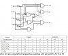
Design a structure of the circuit controlling the work of the G1 and G2 heaters via the W1, W2, and W3
switches in dependence on temperature T:
- when T ≥ Ta – G1 and G2 turned off
- when Tb ≤ T < Ta – G1 and G2 connected in series and turned on
- when Tc ≤ T < Tb – only G2 turned on
- when Td ≤ T < Tc – only G1 turned on
- when T < Td – G1 and G2 connected in parallel and turned on
If anybody is good at that, please write to [email protected]
******
Design a structure of the circuit controlling the work of the G1 and G2 heaters via the W1, W2, and W3
switches in dependence on temperature T:
- when T ≥ Ta – G1 and G2 turned off
- when Tb ≤ T < Ta – G1 and G2 connected in series and turned on
- when Tc ≤ T < Tb – only G2 turned on
- when Td ≤ T < Tc – only G1 turned on
- when T < Td – G1 and G2 connected in parallel and turned on