Continue to Site

Welcome to our site!

Electro Tech is an online community (with over 170,000 members) who enjoy talking about and building electronic circuits, projects and gadgets. To participate you need to register. Registration is free. Click here to register now.

  • Welcome to our site! Electro Tech is an online community (with over 170,000 members) who enjoy talking about and building electronic circuits, projects and gadgets. To participate you need to register. Registration is free. Click here to register now.

i need help with my very -very small project...

Status
Not open for further replies.

sizala

New Member
hello friends,
i does not know electronics that much but i know enough .
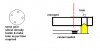
i have a old "pendulum clock" which comes with the lots of gears in it . What i want to do is "remove the big metal globe kind of thing from the pendulum , and put a magnet in place of that metal part . And then i will place a big size of copper wire coil so it can make a small power when the clock is running . so after that it can light a small LED.

my problem is = " the coil can not give that much power to light a LED , so i will need a small circuit which will have a normal capacitor (as i think)
and some thing to trigger that (transistor) when the capacitor is full charged. than the capacitor can light the LED for .5 sec .

but i do not know how to place the capacitor or how to make this circuit , so if any one can help me with this than i will be very thankful to him/her.
if any one finds any thing on this then please send me the link or a circuit diagram .

thankx for reading...
 
Last edited:
First, if the gears in the clock are made of ferrous metal, then putting a large magnet anywhere near it will kill the clock because the gears are going to get magnetized.

Second, the rate at which the pendulum swings past the coil will not make enough voltage to do much with unless there are thousands of turns.
 
thenkx for reply MikeMI,

the gears are made of copper so a magnet will not stop it ,,,,

Second , yes i will put three coils so it can make a some more power .....

and my friend i know that it will make very-very small power which will be the smallest unit on the malty-miter. and that's why i need the circuit diagram...
 
pendulaum is the one triggers the seconds of the clock by its oscillation. the length plays a role in it too. when you use it to convert its power, then you are trying to change its frequency and you will lose the sync with other clocks.

also the power you will get from it will be from the battery or the source of the clock, so if your real concern is to generate power it doesnt make any sence.

if you want to blink a LED when it reaches one end, or both then you use a small megnet on it to oscillate with one/ two whole sensors at ends (fixed) to detect it when it comes near and use some electronic to switch the LED.
if its a mechanical type of clock (spring charged) you shoudl think of some other way to lighten the LED.
 
Last edited:
thenkx for reply mabarazeen,
yes ,you are right my friend there are lots of ways that i can light a LED from the clock by putting sensors in it but that will need a separate power supply.

My goal is to generate power from pendulum's side by side moving. it is not a mater for me that how much time it will take to charge the Capacitor (or light the LED) for one blink .
( and keep in mind that i had already figured it out the coil and magnet part , all i need is just the capacitor and the transistor circuit diagram.)
 
the coil is making 0.4 || 0.5 voltage each time when the pendulum moves over it.. and i do not know about the current and pulse thing....
 
yes my friend i can make the coil bigger than that but tell be about the circuit diagram which can store power in a capacitor ...... any idea about that.??????
 
there are some circuits which are used in small solar robots . they work same like i want in this project . those circuits collects power in big capacitors then it will run motors for 1 sec. this type of circuit will be good enough for my project but i do not know the diagram for that circuit. images **broken link removed**
 
The diagram is given in the instructable page. I show it below. Problem is: it does not "work same like i want in this project". This instructable describes a storage system that uses a few volts DC at several mA.

You have several millivolts AC at an unknown current level, probably a few microamps. The problem, then, is how to convert the minuscule AC voltage to DC when it's barely at the voltage that turns on the best of diodes. Then take that tiny DC and boost it to a level that makes an LED interested in lighting. Then store it in a capacitor before it leaks away. After that, light an LED when there's finally enough.

So here is the instructables circuit. It will not work with your coil.
 

Attachments

  • F2E1HD7KFKET2JY4EM.MEDIUM.gif
    F2E1HD7KFKET2JY4EM.MEDIUM.gif
    12.2 KB · Views: 222
my friend i know about that circuit and also that how it works but my problem (question) is how to make it small in scale(value) so it can work with my coil ... any idea about that????
 
Last edited:
Dear Sizala, I think your problem is simple and if you can understand verbally I will tell you that place and diode connecting the anode to the coil and cathode to the capacitor and use the value of the capacitor 220uF 6or 10 volts. connect your led accros the capacitor and the coil should be connected ...one end to the anode of the diode and the other end to the -ve side of the capacitor. Just see if you are successful otherwise you can contact me on my email ...mub317@gmail.com.


from mub316
 
this type of circuit will be good enough for my project but i do not know the diagram for that circuit
my friend i know about that circuit and also that how it works
I am disappointed that the circuit you asked for is not the one you wanted.
 
mneary,
what i wanted to say there is that the circuit in the solar robot is very big for my project and it is the same type of circuit which i want but i want it in small size (capacity).
GET IT???
 
use a brigne rectifier in series with your coil and then a capacitor (rectify), it wll keep on charging to the peak voltage the coil delivers. use another ratating arangement with a micro switch inside. couple it with a gear turning so you can decide the ratio depends on how frequently you have to on and off your LED. (mechanical on off by rotating disk).

so capacitor will be charged in every oscillation and after certain interval LED would be switched on for a while by the mechanism. or until the cpacitor get discharged.

hope it may work.
 
Last edited:
A bridge rectifier would work if the voltage was above the level needed to operate the LED plus the bridge rectifier, e.g. about three volts total.

OP only has 0.3-0.5V, making a bridge rectifier useless.

Maybe someone can find words that will make the OP understand this concept.
 
he has to modify the coil to give enough voltage but less current is ok, the power a pandulum can diliver is very small and need some oscillations to give a charge to lighten a LED for few second. i sugested him to modify it 1st. he can use the idea as attached to build a mechanical switch.
 

Attachments

  • switch.JPG
    switch.JPG
    13.5 KB · Views: 172
hello frends.... this project did not worked ...i am working on some thing new and it is half done......but i am stuck now...please help
 
hello frends.... this project did not worked ...i am working on some thing new and it is half done......but i am stuck now...please help
help
 
Status
Not open for further replies.

Latest threads

New Articles From Microcontroller Tips

Back
Top