Continue to Site

Welcome to our site!

Electro Tech is an online community (with over 170,000 members) who enjoy talking about and building electronic circuits, projects and gadgets. To participate you need to register. Registration is free. Click here to register now.

  • Welcome to our site! Electro Tech is an online community (with over 170,000 members) who enjoy talking about and building electronic circuits, projects and gadgets. To participate you need to register. Registration is free. Click here to register now.

I need help to repair this ribbon cable

Status
Not open for further replies.
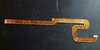
Can anyone suggest what solvent I might use to remove the shellac or varnish or whatever the coating is, from this busted ribbon cable? It's out of an HP Elite x2 1012 G2 tablet and is the "touch cable" which enables the touch screen. The main display cable is fine and I can continue to use the tablet with a mouse and keyboard.

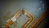
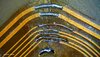
But I'd like to try to repair it if I can. As can be seen from the photo, I managed to bridge the first two tracks but had little success with the 5 thinner ones. The soldering iron kept melting the coating which contaminated the joint. I figured I'd have better luck if I could clean the coating off more effectively with a solvent (rather than trying to scrape it off with a blade). I might need to cut the broken ends back a bit and try to bridge the gap with bits of fine insulated copper wire. I have a good bench microscope for SMT work so it shouldn't be impossible as long as I can get a few mm or so of clean copper on each track.

Needless to say, if anyone can suggest a better alternative method for a repair like this, I'm all ears.

In case anyone is wondering, my first thought was to try to buy a replacement cable which is listed as p/n 924453-001, Cable Kit in the Maintenance and Service manual which I assume means both cables. My local HP can't or won't sell me the cable(s) saying I have to pay them to replace the entire LCD display screen with the cables. This would cost the best part of a $1000/-. I've searched all over for a supplier and can see the Cable Kit listed on many web sites with the price but so far haven't found one either with the part in stock or who can ship to Singapore.
Thanks for reading
Trevor
 

Attachments

  • 20210520_205832.jpg
    20210520_205832.jpg
    445 KB · Views: 581
I've seen them but don't see the one I need. I tried every combination of search terms I could think of but haven't had any luck so far.
 
Just use very fine abrasive, eg. 600 or 1000 grade, to carefully take the top insulation off the flex PCB traces for a centimetre or so either side of the damage.

Then use single strands of wire from a normal multi-strand cable, laid along each trace and soldered down so there is at least 5mm overlap each side of the damage.

For each trace, solder at one side while holding the end of a well over-length bit of shaped wire in place, then cut the free end to length, hold that down with a jewellers screwdriver and solder that side.

If you start out with the strands of wire are 2 - 3 inches long you can easily hold them by hand to position the first end without the part you are holding getting too hot. Bend the end you are gripping or make a small loop in it, so you can control the angle.
 
Thank you for this, rjenkinsgb. It's gonna be a challenge for my 74 years old fingers, but with the little Chinese Andonstar microscope I bought, I might get away with it.

I bought the scope so I could practice SMT soldering for the first time. All my experience prior to this had been with .1" through-hole PCBs using a normal x10 magifier but this is totally inadequate for SMT.

There were one or two .5mm pitch ICs to mount but with the scope and some really helpful YouTube videos about draw-soldering I managed to make a decent job of it.
 
I had success recently scraping the insulation off the general purpose form of this kind of cable (ie, plain ribbon) by scraping across the conductors with the tip of a sharp craft knife. It was easier and quicker and more accurate than using abrasive. I suppose there's an increased risk of causing more damage however.

I was going to suggest 0.1mm magnet wire (cheap on eBay) for the repair, but rjenkins' suggestion is arguably easier. Magnet wire is great if you're used to it...

Hot tip! When you finally get to actually soldering the wires on, tape everything down before soldering. Kapton (or the cheap version, Koptan) tape is ideal, but you could use maskng tape. Sellotape/Scotch tape is stable, but melts too easily (unless you have the very old cellulose stuff). I wouldn't use electrical tape, it has too much adhesive on it and is too stretchy. Tape the ribbon to the bench, tape your repair wires to the ribbon. When you've soldered one end, tape down the end you soldered before soldering the other end (because the solder will melt again and the wire will move and your beautiful craftsmanship instantly turns into a botched mess. I speak from experience!). If you feel you can safely cut the wires after they''re soldered in place, it's easier to use long strands and trim them after soldering. (But it's more important to not do more damage, obviously)

There are at least a couple of YouTube videos showing repair of these cables, might be worth a look.
 
Thanks again, throbscottle for the great tips. I've got the cable taped to a piece of fibre glass PCB and that's taped to the base of my scope so nothing moves.

I managed to get a couple of mm of the ends of each broken track tinned and then soldered in two bridging wires successfully. I was able to use regular Cellotape to anchor one end of the wire with the other end cut to correct length so I only had the spare wire at the anchored end to remove. In practice I found there was no problem caused by the heated wire melting or softening the adhesive. Speed soldering the joint is key.

I've never seen or used "magnet wire" but the best wire I could find was a single strand from the centre core of some RG-174 coax which is .15mm dia, bare copper. It worked fine once anchored adequately and didn't need to be pre-tinned.

Only 3 more to go! I'll post a shot of it if I can complete it successfully without getting over confident and botching the whole thing.
Thanks again
Trevor
 
Well it ain't pretty but it's electrically OK. I encapsulated it with some epoxy resin which should help keep the damaged section rigid. Once it has fully cured, I'll re-install the cable and keep my fingers crossed it works. It was pretty much a nightmare working at such extreme manification but as I've said, the biggest problem was the conformal coating that kept melting into a chemical sludge all over the joint. Acetone nail varnish remover had no effect. Gentle scraping works fine for cleaning the copper but the coating between the tracks need to be cleaned away. If I'm ever clumsy enough to damage a flex cable again and try to repair it myself, I'll put more effort into tracking down the right solvent to get rid of that coating completely before trying to solder.

Still can't figure why it's so difficult to buy a new replacement. As I said in my first post, HP insisted on replacing the LCD display with the two cables attached and doggedly refused to accept that the cables are listed as a spare part with a part number despite me pointing this out in the very same maintenance manual they sent me. After all, the tablet is out of warranty and has been out of production for about 4 years.

My guess is they just don't want to release parts to retail end users for self repair. That could well be just local policy. HP Partsurfer in the US/UK lists the cable kit and even quoted the price in Sing dollars but will only ship to their home country. That would be fine but they have no stock and seem reluctant or unable to say when they will have them in again. There seem to be no shortage of similar cables for other models on eBay and elswhere but not for this one.

Many thanks to you and rjenkinsgb for all the helpful advice.
Trevor

EDIT: Happy to report my repair worked! My touch screen is working again. Phew!
 

Attachments

  • PICT0003.jpg
    PICT0003.jpg
    138.7 KB · Views: 416
  • PICT0004.jpg
    PICT0004.jpg
    101.8 KB · Views: 312
  • PICT0005.jpg
    PICT0005.jpg
    143.3 KB · Views: 332
Last edited:
Nice looking repair. It's at least as good as anything I could ever do - well done!
 
Status
Not open for further replies.

Latest threads

New Articles From Microcontroller Tips

Back
Top