Continue to Site

Welcome to our site!

Electro Tech is an online community (with over 170,000 members) who enjoy talking about and building electronic circuits, projects and gadgets. To participate you need to register. Registration is free. Click here to register now.

  • Welcome to our site! Electro Tech is an online community (with over 170,000 members) who enjoy talking about and building electronic circuits, projects and gadgets. To participate you need to register. Registration is free. Click here to register now.

I need an adjustable power supply

Status
Not open for further replies.
I will almost certainly add meters to the polished article but I don't have much faith this current project will be it (just the way I tend to work when it comes "prototypes").

What I'd really appreciate some advice with (apart from the component choices) is terminals. So many devices have so many different types of connectors it's always a party-trick trying to cleanly attach a positive and negative to something while operating the supply etc.

Getting back to the capacitors and my lack of understanding their usage. I know they are rated by their capacity to store energy and the voltage they can pass and I know there's a formula to calculate the value required but is their a general rule of thumb the layman can easily understand?

Also, do I need to fit a heatsink to the voltage regulators?

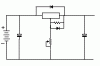
EDIT: I think I've drawn the circuit made. Sorry it's so poor and incomplete, I can't find any programs that I can fathom how to use or allow for simple file exporting in a common format.

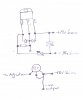
So the next step is to make this a dual regulated supply. ie, one supplying ~12v while another ~4v but they share the same circuit IYKWIM. I'm thinking of replicating the single supply and inserting it in parallel to the source or after the source's capacitor?
 

Attachments

  • PSU1.GIF
    PSU1.GIF
    2.7 KB · Views: 208
Last edited:
Good grief! Seems like I can't even join-the-dots anymore without fouling things up! What have I done wrong, it worked on the breadboard? :confused:

First attempt I'd connected the source power to the wrong connection and could smell something getting too hot. Correcting the wiring, testing then gave 28v through the complete pot adjustment except at the very end when it dropped to ~1.3v

Assuming I'd damaged a component, I made a second board with new components only to have the same outptut reading - 27v until the very last adjustment where it drops to ~1.3v

This is how I built the circuit;-
I have one diode cathode to LM output and anode to LM input.
Other diode cathode to LM adjust and anode to LM output.
A pair of 240Ω resistors in parallel between LM adjust and LM output (same as diode above).
The pot has outer and centre leg soldered to source negative and other outer leg to the LM adjust (before diode and resistor).

The only component I haven't added is the output capacitor which I'm assuming wouldn't cause this problem anyway.

There are no short's I'm certain but whatever the mistake is, I seem to have made it twice. Can only tell what it is? I'm totally baffled.
 
Are you completely certain you have the diodes facing the correct way? You seem to have your anode/cathode mixed up in the above (the diagram is correct). Current flows from the anode to the cathode. The cathode is usually indicated by a stripe on the device.

There should be one with the cathode (stripe) on the regulator input and anode on output, as well as one with cathode on output and anode on adjust.
 
Hi Dalaran and thank you for responding. In answer, no I'm not sure of anything now but you're right, I misrepresented the diode, I meant the striped end which I wrongly called the anode - my bad.

I just built it a third time (lucky I bought five LM's!) from memory as I know this circuit off-by-heart - this time on the breadboard again and it works fine. I've obviously got some mental block translating it from breadboard to soldered board.
 
Hi Tipsy. It can be a little discouraging when you solder up a whole circuit and then find it doesn't work. We all do that too! :D

You could try soldering it up a bit at a time. So you would connect up just the LM317 and its resistor and pot, then double check the pins are right, then power it up and test with your voltmeter.

The output voltage should vary ok and there will always be 1.2v between the output pin and the adjust pin, the adj pin is the one connected to the pot.

If that is ok, you can solder in the 2 caps Cin and Cout and test again.

Then finally the diode(s) and that important cap across the pot (from adj pin to gnd).

It's hard to blow up LM317 regulators so you might be lucky and still have 5 good regs.
 
Hi Mr RB, as I lay my head down to sleep last night, this issue was running marathons around my mind and I came up with that very suggestion! Proves that old adage K.I.S.S. is the answer - well it suits me. :D

If I can find where the cat's have hidden my veroboard, I'll get onto it asap but some late Christmas shopping is required so it may not be for a while now.

On that note, I would like to wish you and other forum members a Merry Christmas - peace and goodwill wishes to all.
 
Fortunately, the masses were not at my local high street and I got my shopping done with time to spare so back to the bench I came...

Lessons learned;
1. If you teach your nephew to solder, check for any excess that might have formed behind the POT's terminals causing a short :rolleyes:
2. Make sure you always use the same POT terminals when testing the POT or using it to compare one circuit to another.

It was just unfortunate that I used one outer terminal for the breadboard and the other for the soldered circuits but what odds to do that several times??? I did say in a previous post that I seem to have a knack of doing things the hard way.

Anyway, I'm happy to announce I now see a range of 1.10 to 17.05v. However, I'm also seeing a range between Output and Adjust of 0.35 to 1.08v which you appear to be suggesting should be a static 1.2v?

That was from the first soldered circuit - that I'd dismantled leaving just the LM, the POT and the resistor (116Ω).

Switching (no pun intended) to the second soldered circuit I made (which is with the diodes but not the caps), I get a nice adjustable range of 1.10 to 17.00v

And again between Output and Adjust, a range - 0.68 to 1.11v

Besides the above results, of which I'll await your comments, I'm glad you mentioned the caps Mr RB as I'm still unsure of which values to chose and wasn't aware the POT to Negative cap was important, thank you.
 
Could you please post info on your parts values and any other details.

Can you post a picture of the wiring of the LM317 pins (or even just draw it?).

0.7 to 1.1v does not sound right for the voltage from Vout to Adj pins on the LM317.

LM317 operation is very simple; if there is less than 1.2v from Vout to Adj the LM317 turns hard on and the output voltage would be high (around 2v less than Vin).

I think you may still have it wired wrong and the pot might be directly supplying your output voltage, not the LM317.
 
Yup agreed, my supply is VERY stable with a minimum output voltage of 1.26V.

Also it shouldn't matter if you connect the pots left outer terminal and middle on one project and the right outer terminal and middle on the other. It's just that CW rotation of the pot will increase voltage in one case and decrease in the other. However if you use the 2 outer terminals it in fact acts as a fixed resistor.
 
I've sat down and tried to draw my circuit but while double-checking the LM pinouts I'm reminded that I never was 100% sure of the orientation shown in the datasheet - I just assumed from the results I'd got it right. So can someone please confirm what the datasheet refers to as the "top view". If you differentiate the printed side from the heatsink side, I'll know for sure.

In the meantime, I'll see if I can get my hand-drawn circuit 100% accurate and scanned in.
 
Attached is my poor effort at drawing the circuit. In the UK, we use the rectangle to represent a resistor. In my case, I had to parallel a pair of 231Ω giving a total reading of 116Ω

I have yet to add the output and adjust capacitors, hence they're not shown. I've also included how I've wired the pot just to be sure I've not introduced a mistake there.

If I've got it right, the diode stripe is on the right side.

Capacitor = 100µf 25v
Resistor = 116Ω
Diode = IN4001
Pot = 5KΩ

I hope that's clear and thank you for taking the time to assist me.
 

Attachments

  • PSU1.jpg
    PSU1.jpg
    341.3 KB · Views: 200
Your picture is rough but all the wiring looks good.

I checked the LM317 datasheet and you got the pins right and all the parts are in the right place. The only things I can fault is that you need an output cap from Vout to ground and a cap from adj pin to ground (or across the pot).

But other than that it looks ok.

How are you measuring the voltages? And have you tried attaching a load to it (like a resistor ar a light bulb etc)?
 
Please don't assume I've got the LM pinouts correct as I couldn't tell from the datasheet which side is facing out - the printed side or the heatsink side? In my drawing, you would be seeing the print. Is that correct?

I'm still unsure how to value the cap's as each example circuit I read uses different values. I have a selection box of disc types and electrolytic types to choose from.

Voltage readings are taken unloaded. I will try and find something to load it other than LED's.
 
Last edited:
Now added a 10µf cap across the outputs and same across the POT. Using a 12v 0.17a PC fan, max voltage now reads just a lowly 7v.

Voltage is still variable across the OUT and ADJ - 0.7v when output at maximum and 1.19v when output reduced to 1.27v.
 
Last edited:
That sounds like you have it wired wrong,it looks like the fan is being supplied through the resistor, not the LM317.

My LM317 datasheet shows the pinout on a 3 dimensional picture of the device, there can be no error. You can download it here;
https://www.romanblack.com/LM317.pdf
it also has clear simple schematic diagrams of PSUs and how to connect the diodes etc.

Don't get discouraged! You are very very close to getting it working perfect. Have a look at the new datasheet and check your pinout. :)
 
Well that datasheet confirms I do have the LM orientation correct and the pinouts right so the problem must be in my construction layout. I'll have to go back to the breadboard (where I didn't have these problems) and get the complete circuit working before moving onto a soldered board. Thanks for supporting me through my errors Mr RB (and other contributors), I do appreciate it very much.

My problem might be compounded by a faulty pot - it seems to give almost infinite resistance intermittently, particularly frequent when moved/used and it's the only 5K pot in the "lucky bag" of pots I bought.
 
I'm completely stumped now as I'm still getting a variable 0.3 to 1.0v between Adjust and Output and I've only added the pot and resistor. The output works as expected, driving the fan as a load while showing 1.0 to 15v on full Pot adjustment range.

Is it my sequence (see below)? i.e. The position of the joins? My logic says not but what do I know.

I inserted the LM into a veroboard, bent the Adjust leg (Pin1) back and soldered the resistor to it's very end. Bent the Output leg (Pin2) forward and soldered the other side of the resistor to the very end of the leg. Then soldered Pot to Adjust leg and +ve source to Input leg(Pin3) with the other Pot terminal to the -ve source. There are no further components at this stage.
 
And you are still using the 120 ohm resistor and 5k pot? If so it should be working.

If you don't mind, can you do something to test it;

Adjust the pot so the output is 10v (10v from Vout to ground). Then measure voltage from Vin to ground, and from Vout to Vadj.

Then connect the 12v fan between Vout and ground (don't change the pot adjustment or anything else) and measure all those voltages again.
 
hi.
Where on the South coast are you located.?
 
Status
Not open for further replies.

Latest threads

New Articles From Microcontroller Tips

Back
Top