Continue to Site

Welcome to our site!

Electro Tech is an online community (with over 170,000 members) who enjoy talking about and building electronic circuits, projects and gadgets. To participate you need to register. Registration is free. Click here to register now.

  • Welcome to our site! Electro Tech is an online community (with over 170,000 members) who enjoy talking about and building electronic circuits, projects and gadgets. To participate you need to register. Registration is free. Click here to register now.

I had a PCB professionally produced, Take a look

Status
Not open for further replies.
I think im in the right forum now...

After doing a couple of PCB designs for a mate I was eager to design my own.

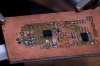
I came up with the idea for circuit that converts a decimal/hexadecimal number from a matrix keypad to a binary number .
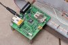
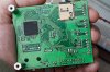
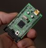
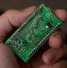
This is basically what the PCB does.
By using a 74HC164 shift register, It is possible to get 8 bits/a byte of data from the outputs lines.

It also has push-on push-off outputs and momentary on outputs.

It comes in handy for things like manually testing LCD's or chips that require an SPI interface.

It is shown assembled on my new site and there is also a YouTube Video: http://jakeselectronics.x10hosting.com

Or click the attached file to see the PCB...
 

Attachments

  • Keypad-Interface-PCB.gif
    Keypad-Interface-PCB.gif
    324.6 KB · Views: 493
Very nice.

It's always cool to get your first board back from a board house.

Hehe. Arragement.
 
Nice attractive and well laid-out board. :)

About the only thing I can fault is that with the 0.1uF decoupling cap on the 16F628A I would have made it closer to the PIC Vdd and Vss pins with much thicker tracks. And maybe the 8 vias under the PIC, they are too close and possibly might short. I would have made them staggered or put some outside the PIC.

You could also have used solder mask over the vias which again reduces chances of shorting but that's a personal preference. Also I'm not sure about all those little orphans under IC2.

But all in all it's very nice. Congrats. :)
 
Based on the other post, it looks like he had this made by Futurelec, so options for things like masking the vias is pretty limited if not non-existant.

Futurelec is a non-option for me, since their minimum 10mil trace/space rule means every chip with a popular 0.5mm lead spacing is unworkable.

It also seems pretty expensive. I just priced a single DS 10cm x 10cm board and was quoted $71 USD. 10 would be $161 USD. For $100.00 USD you can get 1000 square cm of DS with solder mask and silkscreen at Gold Phoenix and 7mil trace/spacing, shipped.
 
Hey DirtyLude

Yeah I've been keeping my eye out for other PCB manufactures.
Here in australia I had a quote and it was about 3 times the price futurlec did it for. The quality would have been better, but 3 times the price just wasnt tempting.

A bit more research in the production stage couldn't have hurt, but I was too eager.
That will teach me.

Overall the quality is pretty good. The silkscreen could had been alot crisper, but NOW i know.

Maybe ill try Gold Phoenix next time.
Thanks for the tip.
 
A bit more research in the production stage couldn't have hurt, but I was too eager.
That will teach me.

I found it to be difficult without someone else doing a very detailed audit of your schematic/board layout to get everything perfect the first time. Invariably you'll have some minor issues. I labeled GND and 3.3V on one of my boards incorrectly, and spaced some header pins badly on another.

Maybe ill try Gold Phoenix next time.
Thanks for the tip.
GP was just an example. There have been discussions here of boardhouses and prices. Unfortunately most are centered around NA and shipping to NA.
 
Last edited:
I found it to be difficult without someone else doing a very detailed audit of your schematic/board layout to get everything perfect the first time. Invariably you'll have some minor issues. I labeled GND and 3.3V on one of my boards incorrectly, and spaced some header pins badly on another.

Can I see some of your PCB's?

And how about this one. you may have heard about them. They are in canada. They are just going into public PCB production.
What do you think of their prices?
**broken link removed**
 
Can I see some of your PCB's?

And how about this one. you may have heard about them. They are in canada. They are just going into public PCB production.
What do you think of their prices?
**broken link removed**
I've seen the dipmicro one and I was thinking about it. I did the quote thing and I don't remember what it came out to, but it still seemed a little expensive. They just started with this so I'll wait for someone's reviews.

I'm sure I've posted these before, but these are SAM7 development boards I had made up. I etch my own boards and I don't sell anything, so I don't have much of a call for a boardhouse, but the ARM7 chips are just too complex around the chip with the seperate core power and PLL and all the decoupling caps to make anything home etched all that pretty.
 

Attachments

  • 20090521-w5300-sam7-001.jpg
    20090521-w5300-sam7-001.jpg
    242.5 KB · Views: 283
  • 20090527-w5300-sam7-002.jpg
    20090527-w5300-sam7-002.jpg
    240.6 KB · Views: 244
  • 20090710-prototype-002.jpg
    20090710-prototype-002.jpg
    224.3 KB · Views: 265
  • 20090710-prototype-003.jpg
    20090710-prototype-003.jpg
    259.3 KB · Views: 291
Those boards were done by BatchPCB because I just wanted individuals. BatchPCB uses Gold Phoenix for their manufacturing. I got three boards in total, all different designs for $46 shipped to Canada. One board is not shown.

I populated the boards myself. Regular soldering iron.

I'm going to be doing some boards for my RF project here and I'll want a few of them, so I'll likely be going directly to GP for that.
 
Last edited:
arr ok. Nice soldering job with the IC.

RF boards ey....
Im interested in getting some RF modules and want to learn about them.

Ill be interested to see your design.

Jake.
 
I've been trying out the TI CC2500 and the Microchip PICTail PLUS modules, but I'm working now with the RFM12B. Google 'jeelabs' and he's doing very similar to what I'm doing except I'm using MSP430's. I'll have remotes and nodes for data collecting and remote operation. It'll be working off a fairly simple P2P network that I'm just adding some complexity too. Trying to get the power requirements as low as possible for nodes that need it.

20090930-lcd7110-thru-pcb-001-jpg.33906

20090809-rf-node-photo-002-jpg.34167
 

Attachments

  • 20090809-rf-node-photo-002.jpg
    20090809-rf-node-photo-002.jpg
    249.3 KB · Views: 592
Have you tried a toaster oven or electric frypan for the SMD?

It gets really easy once you get used to the preheat/solder time cycle and how much solder paste to use.

Considering how many PCB making threads there are I'm surprised there's not more threads on here about doing SMD reflow soldering. It's easier than making the PCBs...
 
I keep thinking about a toaster oven, but I can do leaded SMD quickly. For leadless packages like QFN's I have a hot air rework station that works really well.
 
The Weller portasol PSI-100k and Master Ultratorch UT-100 with hot gas nozzle work well on butane. Less 'wind' to move parts around and hotter output then hot air tools.

Of the two, I like the Master Ultratorch better.

When I have to build more then six copies I get a solder stencil made. Tape down datum boards and use business card to squeege on solder paste. Then on to hot plate.
 
Last edited:
Status
Not open for further replies.

Latest threads

New Articles From Microcontroller Tips

Back
Top