Continue to Site

Welcome to our site!

Electro Tech is an online community (with over 170,000 members) who enjoy talking about and building electronic circuits, projects and gadgets. To participate you need to register. Registration is free. Click here to register now.

  • Welcome to our site! Electro Tech is an online community (with over 170,000 members) who enjoy talking about and building electronic circuits, projects and gadgets. To participate you need to register. Registration is free. Click here to register now.

I am in a bit of a JAM - Update Result pics...

Status
Not open for further replies.

oRIDDLERo

New Member
Here is my situation I have a few RGB LED's

Found here **broken link removed**

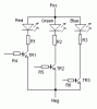
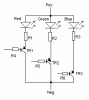
This unit uses a common anode (+) with a lead for each to activate each color to ground. The problem it I have positive voltage as a signal for each leg when I should have a ground signal to illuminate the LED. I figure the easiest way to attack this is with a NPN switching transistor (I think a small relay per leg would be overkill) the problem is I am a total NOOB when it comes to transistors! I read the "Transistors Explained" FAQ and have learned that I need at least .7v to the base of the chip. (can I just use 3v to the base when the collector is connected Gnd and the emitter is connected to one of the multiple cathodes of the LED… This sure would make things easy) if not what the heck resister should I use to get a perfect .7v base signal out of my 3v? How about 5? Am I going about solving this problem the right way?

I consider myself to be a fairly intelligent individual but Ohms law always seems to elude me… lol all I need to lean is how to choose the right resister to attain a needed voltage. I just don’t get it! But that is another story :) Thankyou kindly in advance for any help I get here.
 
As the output acts as a current sink, you've got to use a PNP transistor, and these are a little different to the common NPN ones. Here's a circuit and comments are welcome.
Rx should be ((Vcc - LED Voltage drop) /LED Forward Current)
I use 220ohm for 5v, 330ohm for 6, 1k for 12.

Circuit drawn on MS-Paint for a change as my ball-point is on a break.
 
Oh my god! we got a trouble out here. McGuinn, I tried to delete one of your attachments and oh! hell! the script deleted both of them. You'll have to re-post the schematics.
Sorry for the trouble.
 
Transistors as switches

Chill out Riddler,
The resistors you require are easy to work out ...
See attached drawings

The spec for the RED LED says 20mA with typically 1.9v dropped across it.
For the GREEN and BLUE it says 10mA with typ. 3.5/3.6v dropped.
The important thing here is the current - the voltage is a by-product of the LED's internal resistance.
OK so I can assume your power supply is more than 3.6v.

I guess the supply is 5v and do some sums (Ohm's Law V=I*R)
For the RED LED...
If the LED drops 1.9v there will be (5-1.9) 3.1v left for the resistor.
R=V/I so R = 3.1v/0.02A = 155 Ohms (R1 in my diagrams)

For the others (about the same as each other)
the LED drops 3.5v so there is (5-3.5) 1.5v left for the resistor.
R=V/I so R = 1.5v/0.01A = 150 Ohms (both R2 and R3)

For NPN switching transistors I like BC107, BC108, BC109 (easy for me to get), any small, low power transistor will do.
A positive bias is required on the base to turn it on, as these transistors have a current gain (hfe) of around 500 and you want them to pass 20mA (for the red LED) you must supply at least 0.02A/500 = 40uA to the base.

Assuming you have a 5v signal to turn the transistor on and the base-emitter junction drops 0.7v when working... (more sums)
R=V/I = (5-0.7) / 0.00004A = 107k.
As this is the MINIMUM and the transistor can cope with 5v into the base (it just wastes power!) I would use 47k or so for all the base resistors.

For PNP transistors the sums are different but only because we are now using the transistors differently (the first cct was common emitter, this is common collector or emitter follower)!
R1, R2 and R3 are calculated the same but we should now include a further 0.7v dropped across the transistor's base-emitter junction, leaving 2.4v for the red LED and 0.8v for the others.
R1 is therefore 120 Ohms
R2 and R3 are 80 Ohms

R4, R5 and R6 can be dumped - emitter-followers are self regulating!

So now you have two ways of doing it, depending on your switching signal ...
Positive signals will turn on the NPN transistors
Negative (connect to 0v) will turn on the PNP transistors
 

Attachments

  • TriColourLED-NPN.gif
    TriColourLED-NPN.gif
    2.7 KB · Views: 847
  • TriColourLED-PNP.gif
    TriColourLED-PNP.gif
    2.7 KB · Views: 840
Re: Transistors as switches

mechie said:
Chill out Riddler,
The resistors you require are easy to work out ...
See attached drawings

Thank you so much, you have driven into my head at least the part of ohms law that I need the most (how to find the right resister)

I am on my way to radio shack to pick up some NPN transistors for my little project, when I am through I will post many pictures of my project so you can see the results if you are interested :) .

One more question I am running the blue and green lead off of a tiny pre manufactured motherboard. the default voltages for the stock LED's were around 2.2v so i bridged the surface mount resistors to get the +v up to 3 (seems to be the max) the led lights up very brightly but has no resistor ATM (i do not have any overhead voltage to play with so i figured i did not need one) Am i correct?
 
Project completed with NPN transistors

Thank you for all you help!

Project completed with NPN transistors :) Here it is if you want to take a look at the fianl project

**broken link removed**
 
LED Resistors

Riddler...
Just been catching up with your progress ...
Ace looking XBOX !

You asked about resistors for the blue and green LEDs - YES USE ONE!
An LED is driven by current, not voltage- you have no current limiting device in the circuit beyond the power supply's limit of 3v.

For an LED you should be measuring current (in series with the LED), not voltage, the figures in the spec sheet are typical, don't rely on them.

It may be OK (as you have proved this time) to rely on the supply voltage to remain below the max voltage dropped by the LED at full current but it is a bit risky. You could seriously shorten the LED's life by overdriving it.
Stick at least a ten ohm resistor in series with it (one for each, blue and green), this will not drop much voltage (that seems to contradict what I just said but it is safer!).
 
Status
Not open for further replies.

Latest threads

New Articles From Microcontroller Tips

Back
Top