Continue to Site

Welcome to our site!

Electro Tech is an online community (with over 170,000 members) who enjoy talking about and building electronic circuits, projects and gadgets. To participate you need to register. Registration is free. Click here to register now.

  • Welcome to our site! Electro Tech is an online community (with over 170,000 members) who enjoy talking about and building electronic circuits, projects and gadgets. To participate you need to register. Registration is free. Click here to register now.

Hybride SMPS controller

Status
Not open for further replies.

em2006

Member
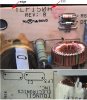
I'm trying to repair a SMPS type TLP150(H?), detail1.png.
It refuse to start. During testing, I connected it by means of protection trafo 1:1 and having a load resistor on the output.

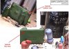
I suspect the hybride IC. The hybride is marked:
YLO 10
KSEI

(attachement detail2.png)

I've looked online and haven't found anything (I searched for hours on this one).
I need your help, a datasheet or any information about hybride spmps controller, or sugest to substitute it.
Does anyone know a equivalent or a place to buy it?

I found somethings about TLP150R power supply, but is not my model, and don't know if it contain
or not the above mentioned hybride.

Thanks,
Emil.
 

Attachments

  • detail1.jpg
    detail1.jpg
    56.4 KB · Views: 375
  • detail2.jpg
    detail2.jpg
    65.1 KB · Views: 446
Often such devices can't be found, or their datasheets - however, common faults on SMPSU's are the startup resistors, or electrolytics associated with them.
 
Many thanks for quick and useful response.

To discover electrical schematic diagram, i was drawed the component side of the PCB (attachement: smps_pcb.png)

Is it sufficient to identify the startup circuit?
May somebody indicate, in this stage of work, the startup components?
Please, reply.

Anyway, my intention is to finish "translate" draft PCB
into schematic diagram, to understand how it work.

I stil can't find the datasheet or informations about hybride.
May be somebody help me...

Thanks again.
 

Attachments

  • smps_pcb.png
    smps_pcb.png
    61.5 KB · Views: 827
Nigel Goodwin said:
I would check R13, R33 and C13.

R33 = 820K = OK.
C13 = 47uF/50V = OK (LC tester Velleman DVM6243, scale 200uF)
Cap is OK, but I don't know about ESR...)

You suggested to check R13 also. But R13 does not exist on the PCB!
Looking for R13, to my surprise I found two references R14:

-R14=10Kohm between pins 6-9 of hybride (test=OK)
-R14=200K/2W = pin8-hybride/+320Vbridge, unfortunately, test=OK!
May be one of these is R13. May be is twice 14 to avoid 13!!!
(see detail3.jpg)

Of course, pin8/hybride take the start voltage via R14-200K/2W (!)
May be fault hybride at pin 8...

What can I do?

R13... suspect, C13... suspect. Too much 13 !!!
 

Attachments

  • detail3.jpg
    detail3.jpg
    70 KB · Views: 323
Status
Not open for further replies.

Latest threads

New Articles From Microcontroller Tips

Back
Top