Continue to Site

Welcome to our site!

Electro Tech is an online community (with over 170,000 members) who enjoy talking about and building electronic circuits, projects and gadgets. To participate you need to register. Registration is free. Click here to register now.

  • Welcome to our site! Electro Tech is an online community (with over 170,000 members) who enjoy talking about and building electronic circuits, projects and gadgets. To participate you need to register. Registration is free. Click here to register now.

Hybrid PSU linear stage help with some values please!

Status
Not open for further replies.

throbscottle

Well-Known Member
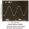
I arrived at this design for my PSU's linear output stage and tweaked it in LTSpice until I got a nice linear rise in output as the control voltage is changed.
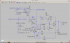
So what we're looking at is a mains transformer/rectifier/smoothing producing 49V, a switching stage (represented by V1 and V4) which tracks the output and produces around 5-35V, and this linear stage, which will eventually have an adjustable current limit. I didn't think it necessary to regulate the low voltage supply for the op-amp.The output is adjustable from 0 to around 30v

V2 represents a 1.2V reference (ICL8069DCZR because they were cheap on eBay) with a 47K multi-turn pot across it (again, cheap on eBay),

I chose TIP42 as the pass element again because of cost, and LM324 I already have. BC547's I have a lot of old ones, that's why I'm using those.

I think that Q2 and Q1 should be thermally coupled, but I'm not sure.

I found that putting in R2 makes the output more linear, but I don't understand why. Make it low enough and it stops a nasty kink appearing in the op-amp's output at about mid-range. So can anyone explain what is going on there?

Also, I arrived at values for C3 and C5 by trial and error. I'd like to know how to calculate what they should be - so can anyone help me with that?
 

Attachments

  • snapshot2.png
    snapshot2.png
    89.1 KB · Views: 170
  • Draft4.asc
    3.7 KB · Views: 112
TIP42 is around 0.11 ῼ in the 3~6A region

MOSFETs can get much lower easily. Sure you want about this Linear approach?
Also current sensing can be done with 50mV shunt R for protection.
 
TIP42 is around 0.11 ῼ in the 3~6A region

Strange way of putting it?, you don't get a 'resistance' with a bipolar transistor you get a 'voltage drop' - but even then both of these refer to switches, not to linear operation of the devices - if your linear PSU regulator is switched hard ON, then it's not regulating at all, and you're far exceeding the capability of the design (and outputting the full unregulated supply from the reservoir capacitor).
 
Actually all semi's used as switches and diodes including LED's have a fairly constant ESR {rbe, RdsOn, rBE Rce } when saturated.

Only Diodes Inc.(nee Zetex ) are clever enough to actually include this in all their specs.
BJT's used as switches have a Rce spec.

I obtained it from the VI slope in this region.

upload_2015-4-9_15-45-43.png
 

Attachments

  • upload_2015-4-9_15-42-13.png
    upload_2015-4-9_15-42-13.png
    71.9 KB · Views: 135
Cooo-eeee *waves* Guys :) Very interesting but not answering my questions! Don't like to appear rude but,
Why does R2 make the regulator more linear?
C3 and C5 have a big impact on ripple, trial and error is all very well, but I'd like to know how to calculate what they should be!

Thanks :D
 
Your output driver is basically unipolar ( Pullup or source only) which is rather suboptimal compared to bipolar drive. such as complementary emitter follower or complementary MOSFET ( aka cmos)

Adding R2 does 2 things. raises output impedance for sourcing ( by lowering the self-bias current point and lowers sinking impedance from open circuit to 200 Ohms. (Still high compared to 10R load)

The closed loop gain R4/R5=30 also reduces the output impedance by a factor of 30 but only for small signal response.. thus it can track small changes as long as 200R can feed Ic=Cdv/dt on output load.

Conclusion
Sub-optimal uni-polar driver with passive pulldown.

Recommendation

Use complementary bipolar BJT or MOSFET drivers with cross-over distortion control.

Even a bunch of CMOS buffers (ALCV2 type) each with 25 Ohm source impedance bridged in parallel with Rf/Rin feedback would make a better linear pulse driver for driving 1000uF

Loop stability requires Bode Plot and knowing gain and BW of each stage to calculate C for accuracy and stability, which is one way to a buffered Op Amp design.
 
Last edited:
The LM324 quad and its sister the LM358 dual are poor for linear circuits because they produce crossover distortion and are very slow. The distortion causes a kink in a linear ramp. The distortion and slow speed are because the opamps are low power and do not have enough bias current to be linear and fast. Look at what it does to this sinewave:
 

Attachments

  • LM324 crossover distortion4.PNG
    LM324 crossover distortion4.PNG
    52.3 KB · Views: 143
I might consider a complementary MOSFET Class D Amp with PWM control for the input.

But, I'm not sure what your specs are.
 
I beg to differ but nobody makes better saturated BJT's than Diodes Inc who have over 50 patents on the subject.

The voltage rise on Vce(sat) is fairly linear , hence Rce is very useful.
Similarly voltage rise on LEDs, when saturated..... hence ESR is very useful.
 
I'm basically doing a low-budget version of this:
https://electronicdesign.com/boards/simple-switchers-make-simple-pre-regulators
https://electronicdesign.com/site-f...ctronicdesign.com/files/29/6388/figure_01.gif
But this is just the linear portion.

I swapped the op-amp in the original for an op-amp + transistor because of the high supply voltage I have (49V), which means I can use a low voltage OA. Also the original is really expensive.
So the kink in the output if R2 is a higher value (like 1k) is caused by crossover distortion? Fascinating. So I would be better off putting a long tailed pair in there instead of the OA?
Tony, searching on the hoofernet for ALCV2 only produces threads where you've (I'm guessing you are SunnySkyGuy!) suggested it, no data. Can you enlighten please?
Thanks for the useful tip for obtaining ESR of semi's btw, one of those things I want to know on rare occasions.

Apart from the switching pre-regulator this is a general purpose bench psu much like any other. I just want to get the ripple as low as I can and make it as regulated as I can, as cheaply as I can :D
 
Ripple and load regulation have everything to do with impedance ratio for DC or some Z(f) with f ripple where values of ESR in the Cap can be important to know as well as the ESR in the power source.


Historical notes

ALVC2 ( corrected) comes after a long lineage when life was simple and all we had was '54/'74 '74S '74L '74LS '74F '74HC '40xx which included a migration from TTL to CMOS with pin compatibility. The prefix ' was generally the vendor code and we usually preferred Fairchild for speed and low impedance.

Then were improvements in speed and lower impedance drivers with more consistency between vendors. So the prefix didn't matter as much and SN74ALSxx became 'ALSxx... in abbreviated form.

Some offspring were 'HC 'AC 'AHCT 'ALS 'ALC 'ALVC

Which brings me to ALVC2 , which is what I meant not ALCV2 :(

All the Atmel processors use this 'ALVC2' driver design which has a low voltage drop at rated current equivalent of a 25 Ohm ESR or RdsOn as it is , and both are N and P are chosen equal.

When CMOS came out, I have used it for Analog purposes with Buffered types having a gain of 1000 with stages of inversion or Unbuffered with 1 stage inverter or a gain of 10 so it could be used with negative feedback as a cheap and dirty self- biased AC amplifier.


I grew up as an Engineer, learning with the likes of R.A.Pease, J. Williams and Burr-Brown
and read every Design Note published and bound in our EE library before my grad. in '75 so I could design from their experiences and applied it to my 1st job in aerospace.

Tony
aka.a Sunnyskyguy

p.s. If you deviate from a published design, try to figure out the assumptions not stated in the parts specified like ESR in coils (Rs) , caps, transistors (RdsOn, Rce) and have good reason to change and understand the implications on bias. e.g. All transistors are rated Ic/Ib=10 because hFE no longer applies when saturated. Except Diodes Inc use a ratio of 20 to 50 because they figured out how to saturate with better performance and lower bias current by improving the Rce value. ( special doping and geometry)

Note that https://electronicdesign.com/site-f...ctronicdesign.com/files/29/6388/figure_01.gif
does not state the critical Rs for L1 and RdsOn for Q1 as these are affect cost, current, load regulation, ripple and load specs which are user design parameters and are key parameters.

N.B. Always start with a good spec. then have a benchmark to test your design.
You can always change the spec, if it fails to meet your cost target or performance trade-off.
 
Last edited:
I'm basically doing a low-budget version of this:
https://electronicdesign.com/boards/simple-switchers-make-simple-pre-regulators

Apart from the switching pre-regulator this is a general purpose bench psu much like any other. I just want to get the ripple as low as I can and make it as regulated as I can, as cheaply as I can :D

Basically any cheap and dirty Buck regulator design for 90% efficiency <5% ripple for large V ratios can be followed as your loads are not shown to be reactive so Voltage source high side driver may be all you need.

If you have reactive loads or , you want to bring the voltage down quicker with no load or want lower ripple, then push-pull Buck regulator is better. This is the standard used for low cost PC PSU's with one output regulated and the others track by tight coupling.

https://tpucdn.com/articles/160/images/switching_Push-Pull-converter_small.jpg

Yes your R added gave the minimum passive pull-down needed to drive a large cap with linearity and negative feedback .
 
Last edited:
Thanks for the responses Tony, AG & Nigel, now I have something I can get my head around :)
 
Status
Not open for further replies.

Latest threads

New Articles From Microcontroller Tips

Back
Top