Continue to Site

Welcome to our site!

Electro Tech is an online community (with over 170,000 members) who enjoy talking about and building electronic circuits, projects and gadgets. To participate you need to register. Registration is free. Click here to register now.

  • Welcome to our site! Electro Tech is an online community (with over 170,000 members) who enjoy talking about and building electronic circuits, projects and gadgets. To participate you need to register. Registration is free. Click here to register now.

HP 1740A Oscilloscope - Repair HELP!!!

Status
Not open for further replies.

Barry Fox

New Member
I have had a HP 1740A Dual trace oscilloscope for over 20 years, with a full set of instructions and circuit drawings, and now has a common vertical deflection problem on A, B or chop. Horizontal deflection is OK. The Vertical trace is way south and the vertical adjustment pots have little or no effect. I have digital electronics experience, but no idea what voltages to expect on an oscilloscope.

A old thread by Jim Yanik recommended shorting the vertical deflection plates to each other, which did result in a correct centered trace. All power supply voltages are OK. There was a burnt connector pin and dry joints on the screen illumination side which I repaired.

With the A probe on the Cal 1v, only channel A selected and the vertical position pot on MAX, I can see the square wave pulse at the botton of the screen. Volt on 1st deflection plate 11.36v, 2nd 11.06v. When vertical position pot to MIN the 11.36 REDUCES to 10.49, and the 11.06v INCREASES to 11.24v. Adjusting (lowering) the vertical posion pot only lowers the top part of the square pulse signal trace, the botton trace of the signal is fixed right at the botton of the screen, and does not move.

I do not know what the correct deflection plate voltages should be, or what the difference in the 2 voltage should be for the signal trace to be correct or visible on the screen.

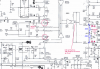
On the input to the vertical deflection card, at the transistors, the circuit indicates +12.6v for both sides. I have measured 12.6v on the one side and only 10.92v on the other side. Base reference voltages on both transistors is correct at 12v.

I do not know what is lowering this 12.6v to 10.92v or if this is the problem at all (beginning of the Vertical output card, or the output of the vertical preamp. )

I am now stuck and at the end of my voltage !!. Can anyone help or advise ?

Regards
Barry
 
hi Barry.
Post a scanned image of the Scopes Yamp's circuitry [ from the manual] , the section that covers the Y inputs to the Y plates will be enough for starters.
 
Last edited:
Hi Eric

I have attached the pdf. (I hope)
 

Attachments

  • HP 1740A - A5 vertical output -0001.pdf
    284.7 KB · Views: 1,076
I would suggest the most likely cause is the large hybrid output device, labelled A5A1? - which is probably only available as a spare part as it's presumably a custom device?.
 
hi,
As Nigel points out it could be that custom output IC.

Looking at Q3 transistor, as its a PNP its is switched hard OFF with those base/emitter voltages shown in 'ink', that would set the collector to the shown negative value.

Can you post the circuit for the other end of the DELAY line input.??
 

Attachments

  • AAesp01.gif
    AAesp01.gif
    86.6 KB · Views: 1,054
Hi Eric & Nigel

Thanks for your follow up.

Voltages in Blue - when wires 5/17 & 5/18 are disconnected from the Vertical amp card.

Voltage on Q5 collector 34v (circuit shows 41.4v). This voltage does not change when disconnecting the 2 wires mentioned above.

Barry
 

Attachments

  • HP 1740A - A3 Vertical Preamp0001.pdf
    360.3 KB · Views: 672
Thanks for your follow up.

Voltages in Blue - when wires 5/17 & 5/18 are disconnected from the Vertical amp card.

Voltage on Q5 collector 34v (circuit shows 41.4v). This voltage does not change when disconnecting the 2 wires mentioned above.

Barry

hi Barry,
Quoting voltages with the wires disconnected dosn't help me..:)

Reconnect and post the actual voltages.
 
Hi Eric

All the actual voltages are in Red as indicated in the circuit, with wires connected.
5/17 = 10.4v
5/18 = 11.0v
 
hi,
OK, I will look it over.

EDIT:
hi,
Please let me know what the pin18 and 19 voltages are, ringed in RED
[with all wires connected, do this measurement first]

Then disconnect pins 34 and 36 , connect a 470R from the wire that you have disconnected from pin 34, to pin35 the +12V, do the same for pin 36.
[disconnect at the 'X''s]

Then check the main Yamp voltages again [the ones you posted yesterday.

Adding the 470R resistors should give you a central Y trace display.
 

Attachments

  • scope2.png
    scope2.png
    541.1 KB · Views: 1,346
Last edited:
Hi Eric

Thanks for the info. I had some stripping to do, to reach these circuits, to be able to take the readings. (Metal plate covering the PCB)

Voltages at 18 & 19 are both 5.7 volts exactly.

I will now proceed with your other modification and advise you of the results tomorrow.

Thanks
Barry
 
Hi Eric

Have done the modification with the results attached. I had to cut the tracks, as the chip is a flat ceramic type, with spring clips on th PCB.

I was a little confused testing voltages on Q2 & Q4 until I figured out they had been replaced a long time ago with 2N3906, which have different pin layouts.

The drawing shows that the originally were HP 1853-0354 - Q1, Q2, Q3, Q4

In the process I shorted out Q4 2N3906 and replaced with a BC557 which is all I had.
(I hope this was OK)

These results are after I replaced Q4

There is no trace visible before or after I shorted out Q4 and replaced it.

Regards
Barry
 

Attachments

  • HP 1740A Vertical Mod -0001.pdf
    275.4 KB · Views: 681
hi Barry,
Looks like the A5A1 block is faulty.
A quick confirmation would be to check the voltages marked with a GREEN ring.

Adding the two 470R has shown that the two left side transistors are correctly biassed. The two transistors inside the right side block are not biassed correctly.
 

Attachments

  • AAesp07.gif
    AAesp07.gif
    300.7 KB · Views: 1,235
Hi Eric

Attached are the requested voltages. I will have to start searching for the Chip ASA1, or a complete vertical deflection card.

Do these voltages comfirm you suspicions ?
 

Attachments

  • HP 1740A Vertiocal Amp additiona voltages0001.pdf
    280.4 KB · Views: 571
Attached are the requested voltages. I will have to start searching for the Chip ASA1, or a complete vertical deflection card.

Do these voltages comfirm you suspicions ?
hi,
The Y plate supply is OK at 42.8V, but one plate has only +2.6V, compared to the other plates 37V, thats why the trace is well off the screen.

I would recommend that you try to locate a replacement for the ASA1 IC.
 
Good morning Eric

Thank you so much for all your assistance. I will search for the IC and let you know the result, if I find one.

Regards
Barry
 
Eric, you da man :)
 
Thank you so much for all your assistance. I will search for the IC and let you know the result, if I find one.

Regards
Barry
hi Barry,
If its your favourite scope, you could design and build on a added PCB, a Y amp driver and bypass the IC.
 
Hi Eric

Not much luck in my search for the spares. Many parts available at a price, for the
1740A, but not the IC or PCB I'm looking for.
I do have an attachment to this scope.

I have seen that there is a possibility to buy complete 1740A on Ebay which can be used for spares at $100 to $ 200.00 in th USA, plus shipping to South Africa.

Unfortunately, I do not have the knowledge to design the circuit or which current components to use.

Regards
Barry

hi,
The eBay spares unit sounds OK as long as dosn't have the same problem as your unit.

Which part of SA are you located.?
 
Status
Not open for further replies.

Latest threads

New Articles From Microcontroller Tips

Back
Top