Continue to Site

Welcome to our site!

Electro Tech is an online community (with over 170,000 members) who enjoy talking about and building electronic circuits, projects and gadgets. To participate you need to register. Registration is free. Click here to register now.

  • Welcome to our site! Electro Tech is an online community (with over 170,000 members) who enjoy talking about and building electronic circuits, projects and gadgets. To participate you need to register. Registration is free. Click here to register now.

How to weld wires in the board of a VCR head?

Status
Not open for further replies.

rodrigopoeta

New Member
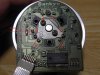
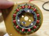
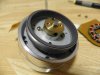
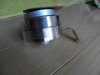
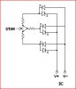
I have a head VCR and I'm intending to use it for power generation and wind generator. However this head has a circuit board to which are attached several coils. At the top of the head board you can see the welds of these coils. Altogether has 6 parts welded. But at the bottom there are 12 coils. The question is In which way should I weld the top to have a three-phase or biphasic? Should I weld the wires directly in the welds of the coils? How to weld? Is it possible to come up with a system in which I have only two wires at the end?

I posted some pictures to help. There is one picture of the top of the VCR Board Head that I put the numbers where the welds are in order to facilitate the explanation.

I thank everyone's help!
 

Attachments

  • P7040049b3.jpg
    P7040049b3.jpg
    108.3 KB · Views: 491
  • P7040063b.jpg
    P7040063b.jpg
    85 KB · Views: 736
  • P7040054b.jpg
    P7040054b.jpg
    66.2 KB · Views: 519
  • P7050065b.jpg
    P7050065b.jpg
    61.2 KB · Views: 358
All very simple, you have a 3 phase motor which you intend to use for a 3 phase generator, all rather standard for a wind generator.

It is a basic motor of 12 coils grouped in 3 groups of 4 coils.

Before you go too far be warned the power output will light a led and not much more, so dont invest too much time, effort and money into this thinking you will develop a battery charger as ...you wont.

Now to answer your question...... as with most 3 phase motors the wiring is either "Star" or "Delta" in the motor above it is configured as "Star" if you follow the tracks on the board you will find 1, 3, 5 are all joined together forming the centre connection of the star, you dont use these points but they do all need to be connected together.

You require to solder (not weld) 2 diodes to each of 2, 4, 6 (6 diodes in total) to form a 3 phase rectifier, this means each pair of diodes will have one diode facing one way and the other facing the opersite way.

Then you connect all the 3 cathode legs of the diodes together and all the 3 anode legs of the 3 diodes together.
The cathodes become the DC+ (positive) terminal and the anodes become the DC- (negative) terminal.

There you have it, your 2 wires output.

I would cut the tracks on the board so none of the other junk was connected as it might draw power, and the other junk is no longer needed, just dont cut the track between pins 1,3,5 or joint them together with a short strip of wire.

Pete.
 

Attachments

  • 3 Phase rec..JPG
    3 Phase rec..JPG
    30.6 KB · Views: 388
Thank you very much for the explanation and for the scheme. Since I don't have knowledge in this area It is a very useful explanation.
I will try to make it and if it works I'll put it here.
 
Just any standard old power diode, 1 amp will do, something like the 1n4004 or 1n4007 it really wont matter as the power will be very low.

Sometimes people use 2 bridge rectifiers and only use 3 out of the 4 pairs of diodes (1 terminal is not used)

Resistors??? what resistors, there is no resistors used.

Pete.
 
Status
Not open for further replies.

Latest threads

New Articles From Microcontroller Tips

Back
Top