hi,
I already search around and i never see a example code for Proximity Inductive sensor including it circuit. If i want use it in PIC18F4550 how should i setup it? example code with description? i also try to simulate in proteus but can not find inductive sensor so i quite blank what to do.
Im beginner in MCU so not much coding i know. Type of coding only i understand a bit is Micro C Pro...
Thank

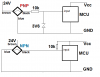
") any sugesstion on what optocoupler to choose for the type of application i'm working on ?? I have done some googling and have found a few but most of em looks to be used for switching Triacs ...
any sugesstion on what optocoupler to choose for the type of application i'm working on ?? I have done some googling and have found a few but most of em looks to be used for switching Triacs ...