Continue to Site

Welcome to our site!

Electro Tech is an online community (with over 170,000 members) who enjoy talking about and building electronic circuits, projects and gadgets. To participate you need to register. Registration is free. Click here to register now.

  • Welcome to our site! Electro Tech is an online community (with over 170,000 members) who enjoy talking about and building electronic circuits, projects and gadgets. To participate you need to register. Registration is free. Click here to register now.

how to test LCD

Status
Not open for further replies.

danae_fiz

New Member
how can i test a 16X2 LCD? do i just connect the Vss and Vdd to source to see if it's working or not? please help. if there's 2 pins with +Vled and -Vled how to connect it so that the back panel light for the LCD is on??
thanks
fiza
 
danae_fiz said:
how can i test a 16X2 LCD? do i just connect the Vss and Vdd to source to see if it's working or not? please help. if there's 2 pins with +Vled and -Vled how to connect it so that the back panel light for the LCD is on??
thanks
fiza

If you connect the power lines and a contrast control (or strap it to maximum contrast), you can adjust the contrast control to see some blocks on one line of the display. It doesn't prove a great deal, but it shows it's not totally dead.

For the back light, simply connect as you would an LED, using a series resistor.
 
connection

this the pin configuration of the LCD that i bought. but my circuit uses different pin.i 'll attach the circuit. i already tried connecting the power and contrast control(20K variable resistor) but nothing happen. does it require a programming for LCD driver??

1-Vss
2-Vdd
3-Vo
4-RS
5-R/W
6-E
7-14:DB0-DB7
15-16:VLED+ and VLED-
(RS stock no. :184-8538)

is this connection correct??Vee =Vo, Vss=GND, Vdd=+5V
thanks
fiza
 

Attachments

  • untitled1.jpg
    untitled1.jpg
    15.4 KB · Views: 2,606
Pretty well all these LCD text modules are standard, they use the same Hitachi chip set (or clones of them) and connect the same. The picture you posted looked to be connected completely wrong, nothing like the pin connections you gave.

Have a look at my LCD connections from my tutorials at which shows how I connect them. The circuit as shown, with 5V applied to it, should light the top row of characters as solid blocks when you adjust the contrast.
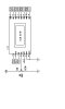
 
thanks

thanks nigel, i'll try to change the connection according to your tutorial and get back to inform whether it works or not.
regards
fiza
 
it works

hi nigel. thank you very much. my lcd is okay now after i changed the connection according to your tutorial.
 
Status
Not open for further replies.

Latest threads

New Articles From Microcontroller Tips

Back
Top