Continue to Site

Welcome to our site!

Electro Tech is an online community (with over 170,000 members) who enjoy talking about and building electronic circuits, projects and gadgets. To participate you need to register. Registration is free. Click here to register now.

  • Welcome to our site! Electro Tech is an online community (with over 170,000 members) who enjoy talking about and building electronic circuits, projects and gadgets. To participate you need to register. Registration is free. Click here to register now.

How to test impedance on a PIC INPUT PIN OSHONSOFT

Status
Not open for further replies.

camerart

Well-Known Member
Hi,
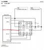
I'm using 18LF4620 PIC 3.3v and an AK8963C compass module.

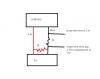
I appears to be that when using SPI, the MISO PIN shows low impedance when it should be high, and this is attenuating the output of the Compass module, giving an intermittent error.

I've tried lots of suggestions over months to find this error, but so far failed. The latest test is by cutting the MISO track. At the Compass side of the cut there is 3.3V and if I check the PIC side of the cut with a resistance meter (I'm sure this sin't the correct thing to do but!) it switches to 33-Ohm when I think the SPI is operating, which results in the Compass output dropping to 1.65V.

Any ideas please?

Camerart
 
Maybe some other SPI device or the pin next to MISO is pulling the MISO down?
Put a pull-up resistor ~ 4.7 kohm on MISO, cut the track to compass and measure the MISO with an oscilloscope.
 
What is connected to what and is it MISO on the pic or compass.

Mike.
 
Have you noticed, that the chip selects of the deselected SPI devices must be in high impedance state or programmed as inputs.
 
What is connected to what and is it MISO on the pic or compass.

Mike.
Hi M,
As mentioned a PIC 18LF4620 is connected to an AK8963C compass chip SPI (directly)

The MISO track is Master in slave out, where the PIC is the Master.
C
 
Have you noticed, that the chip selects of the deselected SPI devices must be in high impedance state or programmed as inputs.
Hi J,
I've been cutting the MISO track for a while now, and since I was getting 'popped' Compass chips I added a 1K series resistor, as I think the hard pull-down was damaging them. I also added a 1K pull-up to the PIC side of the cut/resistor. Shown here:

See note later post!
C.
 

Attachments

  • MISO.png
    MISO.png
    11 KB · Views: 239
Have you noticed, that the chip selects of the deselected SPI devices must be in high impedance state or programmed as inputs.
Hi J,
The SPI sequence is BMP280 READ then AK8963C READ, as mentioned the later one has the Impedance problem, so I swapped them round as TXT '///////////////' This then made the BMP280 low impedance, but still managed to be READ by the PIC, so went un-noticed. Which kind of tells me that if the peripherals has enough 'umphh' it can push into the PIC, or gets damaged (not sure)

I added a level shifter, to the COMP which works, but I've need told that this is not the solution, as the impedance is the solution.
C.
 

Attachments

  • MISO.txt
    3.5 KB · Views: 226
Are you pulling CSB low in order to select SPI? Mike. [/QUOTE said:
Hi M,
Yes.
This has been running for a long time, so all of the SPI settings have been checked.
C.
 
Last edited:
Hi J,
I'm getting strange READings i,e, the SCOPE shows good MISO, but the PIC isn't seeing the DATA.
Sometimes the at rest MISO is high and sometimes low.

I'm sure you recall us trying SW and HW. At the moment I'm using the Oshonsoft SPI settings. When we tried SW HW, it was in order to get 2x PICs to 'talk' to each other. If this is possibly an Oshonsoft fault, perhaps we can try the HW version with the peripherals.
C.
 
Hi,
A friend of mine was looking through the COMP D/S and noticed the low current output from the MISO PIN, here is an image.

Where I was using a 1K pull-up resistor, he calculated a 330K instead.
One of the problems could be the length of my PCB test Wires, connecting the peripherals, he suggested a buffer on the MISO track. As I have a level shifter working on 1x COMP, this would be satisfactory.

Sounds ok to me, I'll adopt it on all COMPs.
C.
 

Attachments

  • Output current and wire capacitance.jpg
    Output current and wire capacitance.jpg
    209 KB · Views: 258
You shouldn't have any pullup on SO. Pullups are only needed if using I2C.

Mike.
 
You shouldn't have any pullup on SO. Pullups are only needed if using I2C.

Mike.
Hi M,
This kind of rings a bell, and I have pull-ups at the moment, because of the slopes in the SCOPE results.

Now I understand that the AK8963 output of 100UA isn't enough to drive the PIC MISO PIN, so I added a level shifter, as a buffer. This appears to be working ok. and doesn't have a pullup. It isn't actually shifting the voltage but boosting the AK8963 100uA to 7MA

C
 
Status
Not open for further replies.

Latest threads

New Articles From Microcontroller Tips

Back
Top