Continue to Site

Welcome to our site!

Electro Tech is an online community (with over 170,000 members) who enjoy talking about and building electronic circuits, projects and gadgets. To participate you need to register. Registration is free. Click here to register now.

  • Welcome to our site! Electro Tech is an online community (with over 170,000 members) who enjoy talking about and building electronic circuits, projects and gadgets. To participate you need to register. Registration is free. Click here to register now.

How to test a resonator frequency?

Status
Not open for further replies.

Doomguy42

Member
Hi I've just got my first oscilloscope (digital) to help me learn more about pcb repairs.

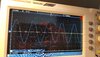
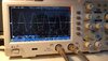
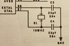
I'm looking to test the resonator clock frequency in the diagram. Is there an accurate way to test or calculate the 16mhz frequency? I can test the oscillating caps and I get 2.9khz. I'm missing a piece of the puzzle somewhere.

Most of these boards are 20+ years old so it would be great to validate the cpu's a correct on what's coming out of the extal/xtal pins aswell if I can.

What should I do?
Huge thanks.
 

Attachments

  • 20200818_001022.jpg
    20200818_001022.jpg
    594.6 KB · Views: 251
EXTAL is the input, XTAL is the driver output for the crystal (or you can just connect a separate xtal oscillator (TTL) to the EXTAL input. use a x10 scope probe (only about 3pf capacitance as opposed to the 30pf of a x1 probe) and test at the XTAL pin, you should have a good strong signal feeding back there into the crystal.
 
Yes, use a x10 probe, if you use a x1 it won't work - the capacitance usally stops the oscillator.

However, those resonators are EXTREMELY reliable - the only ones I've ever found faulty were physically broken. And even the broken ones, you can often manage to solder to the broken stub of the pin.

But using a x10 proibe you should have no problem testing it's oscillating, at about the right the right frequency - check both sides of the resonator (easier than working out which is the output pin).
 
Ok thank you for the replies.... what kind of tolerances are CPU/FPGA clock frequencies? I'm just looking for about the right frequency?
Also the oscillating caps under performing can this be the cause of a poor wave?
If there's nothing either side that would be a cpu/fault?
Thanks again these boards are late 90's SMD and poor quality joints,vias, cmos battery leaks etc I'm just looking to improve my fault finding with them.
 
Ok thank you for the replies.... what kind of tolerances are CPU/FPGA clock frequencies? I'm just looking for about the right frequency?
Also the oscillating caps under performing can this be the cause of a poor wave?
If there's nothing either side that would be a cpu/fault?

That's unlikely as well - oscillators and CPU's are EXTREMELY reliable - and the vast majority that get changed aren't faulty, and don't cure the fault.

But I'll repeat again (seeing as you didn't comment on it) - you MUST, 100% ABSOLUTELY, use a x10 probe if you're scoping the oscillator pins - otherwise you will get either a weak distorted poor waveform (of the wrong frequency) or nothing at all.
 
what kind of tolerances are CPU/FPGA clock frequencies?
Generally speaking microprocessor clock frequencies are not critical, and for the purpose of operating the micro, can be anywhere between 1Hz and the maximum frequency stated by their manufacturer.

However, sometimes the micro clock is used to generate timing pulses for peripheral devices like UARTs etc, in which case the clock frequency should be within (about) 0.5% of the nominal frequency.

the oscillating caps under performing
Usually the capacitors associated with the oscillator circuit are ceramic types and very reliable.
The last place that I would look when looking for an oscillator fault.

Oh, in case nobody else mentioned it:), use a X10 probe on your scope. Otherwise probing the oscillator will probably stop the oscillation.

JimB
 
Crystals are quite common. Take any crystal in the 10 - 20 MHz range (from an old PC, router etc) and put that in circuit. If the circuit now oscillates at the frequency of the trial crystal, the original crystal was dead.

Inside the IC, EXTAL is the input of an inverter, XTAL is the output. Without a crystal fitted, both will sit near mid voltage, as there will be a resistor to keep them at the same voltage. You need a high-impedance voltmeter to check the EXTAL voltage, as the resistor is usually very high resistance.

Any voltameter can be used to check the XTAL voltage. It should be mid voltage with nothing connected, and high when EXTAL is pulled low and low when EXTAL is pulled high. If that is not the case, it may be a faulty IC.

(Don't use any cylindrical watch crystals, marked 32768. They are much lower frequency and they won't oscillate in a circuit made for 16 MHz crystals)
 
Hi thanks again for the fantastic replies.

The probe I have is switchable x10/x1 on the probe... i will double check I have it on the correct setting this evening. Do you still think that's ok or would I need an independant x10?

These old boards I work im sure were full of reliable components but lots have various faults in now in 2020. They had big varta nicad pcb batteries fitted and even on very lightly leaked boards there's odd pockets of rot seem to appear around the board, because some of the components are SMD you get tiny breaks in the traces/pads/under components that's why I'm trying to understand and how to test the areas all around the whole circuit.... cpu included. I might sound silly asking about the caps but i figure if I understand the whole circuit it's only going to help in the long run.

Other people have had a go at repairing some in the past too so they easily could think the caps are decoupling value as they look visually very similar... so I'm just trying to get a picture of what's happening.

Thanks for the fantastic explanations especially on the tolerances and helping me understand how the extal/xtal operate. Totally invaluable gents. :)
 
Last edited:
The probe I have is switchable x10/x1 on the probe... i will double check I have it on the correct setting this evening. Do you still think that's ok or would I need an independant x10?
My own preference is for dedicated X10 probes, but switchable X1/X10 are OK, no problem.

Other people have had a go at repairing some in the past too so they easily could think the caps are decoupling value as they look visually very similar... so I'm just trying to get a picture of what's happening.
The capacitors connected to each side of the crystal, perform two functions:
1 The provide a "load capacitance" for the crystal.
Crystals (well some of them any way) are specified to operate with a given amount of capacitance in parallel, usually abot 30pF.

2 The network of two capacitors and the crystal gives a phase shift of 180 degrees to ensure correct operation of the oscillator.
The other 180 degrees, to make a total of 360 degrees, is provided by the oscillator circuit in the micro processor.

JimB
 
Hi thanks again for the fantastic replies.

The probe I have is switchable x10/x1 on the probe... i will double check I have it on the correct setting this evening. Do you still think that's ok or would I need an independant x10?

As Jim said, switchable are fine - I've never used anything else.

These old boards I work im sure were full of reliable components but lots have various faults in now in 2020. They had big varta nicad pcb batteries fitted and even on very lightly leaked boards there's odd pockets of rot seem to appear around the board, because some of the components are SMD you get tiny breaks in the traces/pads/under components that's why I'm trying to understand and how to test the areas all around the whole circuit.... cpu included.

That's a different story - with corrosion damage ANYTHING can go wrong, including track damage that's underneath components.

Even worse, you might get aboard working - but then it fails again in a fairly short time.

I was given quite a nice musical keyboard with similar corrosion - can't remember the make, but googling showed it was a common fault, and even provided the circuit for it. The damaged chips were all standard TTL ones, and after I'd started working on it I thought - what am I doing?, I can't play a keyboard, I already have a good one, I don't want another - so I binned it :D

As you've got multiple boards presumably that's not an option?, and you're trying to repair products that would over wise be scrap, and possibly not even replaceable.
 
Thanks for the continued help!

I've been able to display the correct wave form on a working board. I had all the settings correct I just needed to up the horizontal scale. I'm guessing it maxed out to whatever the scaling is set at if it's lower...?

Comparing to a board that's faulty and this wave in the picture does not look too good to me. The resonator appears to be at the correct frequency but something is out.

I know I keep saying thank you but I've learned more in the last 24 hours than I have working on my own with a logic probe :)
1/ wave that looks correct
2/ not so good

P.s the boards are uk Mpu based coin opp/quiz/fruit machines. Sadly they always mounted the battery somewhere it would be destructive. It's a great hobby repairing them :)
 

Attachments

  • 20200818_221906.jpg
    20200818_221906.jpg
    1.4 MB · Views: 200
  • 20200818_222052.jpg
    20200818_222052.jpg
    1.2 MB · Views: 196
The waveforms on those types of oscillator are never very clean. In fact, I suspect that the first waveform may be with a crystal that isn't working perfectly.

A crystal oscillator circuit has gain. When that gain exceed the losses in the crystal, the amplitude gets bigger. In a simple oscillator circuit like this one, the amplitude will only stop getting bigger when the input or the output of the amplifier starts clipping, which happens when the voltage approaches the supply voltage or ground. So in normal running, with a good crystal, there will always be some clipping and some distortion of the positive or negative peaks.

The first waveform looks like a very good sine wave. It shows no clipping, and that can imply that the circuit has only got just enough gain for the amplitude to get bigger. Any small loss of gain and it won't work.

If you can set the oscilloscope to dc-coupled input, and tell us what the supply voltage is, that could confirm what is being seen.
 
but lots have various faults in now in 2020.
especially check the ESR of electrolytic caps around voltage regulators and across the +5V rail. these caps drying out can cause lots odd squirrelly problems, especially with TTL logic. it's usually the electrolytic bypass caps and the electrolytics distributed on the logic board at various places that, when they dry out, you start getting a lot of noise on the rail (any more than 50-100mV of noise on the rail is unacceptable, and you can measure this with the oscope). also while on the subject of the rail voltage, the DC rail voltage should be between 4.7 and 5.2V for most classic TTL devices. i've seen TTL run at higher voltages, and the original TTL chips (without any letters between the "74" and the rest of the number) tend to overheat. below 4.7 and operation will be unreliable as well, but not with a thermal hazard for the chips. exceptions are "74C" "74HC" "74HCT" which are CMOS equivalents of TTL chips and they can usually be run at higher rail voltages (usually 12V).... but only if there are no other chips that are non-CMOS...
 
Last edited:
exceptions are "74C" "74HC" "74HCT" which are CMOS equivalents of TTL chips and they can usually be run at higher rail voltages (usually 12V).... but only if there are no other chips that are non-CMOS...

The 74HC are rated from about 2 - 6 V supply. Their input threshold is half the supply voltage.
The 74HCT are rated from about 4 - 6 V. Their input threshold is around 1.5 V so as to be compatible with the 74 and 74LS series.
12 V will kill most 74HC and 74HCT IC

I'm not familiar with 74C series, but I think that they are rated to 12 or 15 V supplies.
 
Comparing to a board that's faulty and this wave in the picture does not look too good to me. The resonator appears to be at the correct frequency but something is out.

I know I keep saying thank you but I've learned more in the last 24 hours than I have working on my own with a logic probe :)
1/ wave that looks correct
2/ not so good

The second waveform looks absolutely fine - exactly as I would expect. Just as Diver300 said, I'm dubious about the overly clean sinewave on the first scope picture - but as it's the right frequency, presumably that's fine as well.

You didn't take them at opposite ends of the resonator did you?.
 
Hi thanks for the replies, after reading I went through a few other types of tech board and as you explained perfectly the wave is distorted.
I will measure the supply voltages on that board as tonight's project. There's two sets of vias to drop the traces below some tracks so I'll check through the vias too.
I checked both sides of the resonator and only found one side to have the distortion... so presumed it was wrong as usual it's me that's wrong :)

Some of these boards only needed very light repairs... in my head they should run- I can see them pop out of reset and load the software bench testing but in the machine they have undesirable effects or go crazy... that's why I'm now trying out the oscilloscope.

Noise on the 5v rail sounds very interesting- I do usually replace 2 electrolytic caps 1 of which ison what I call is the internal 5v (inside a double diode I believe is acting as a voltage regulator).
There are tons more I haven't tried yet. What do I to test this on my oscilloscope? Do I just check the voltage and measure the rise and fall of any fuzz on the line and check is within nominal?

Big thanks all around again :)
 
Status
Not open for further replies.

Latest threads

New Articles From Microcontroller Tips

Back
Top